Parameters 473
94.22 User DC voltage
reference
(Only visible when IGBT supply unit control activated by
95.20)
Defines the DC voltage reference for the supply unit when
94.21 DC voltage ref source is set to User ref.
0.0 V
0.0 … 2000.0 V User DC reference. 10 = 1 V
94.30 Reactive power
reference
(Only visible when IGBT supply unit control activated by
95.20)
Displays the reactive power reference sent to the supply unit.
This parameter is read-only.
-
-3276.8 … 3276.7
kvar
Reactive power reference sent to the supply unit. 10 = 1 kvar
94.31 Reactive power ref
source
(Only visible when IGBT supply unit control activated by
95.20)
Selects the source of the reactive power reference to be sent
to the supply unit.
User ref
Zero None. 0
User ref 94.32 User reactive power reference.1
Other Source selection (see Terms and abbreviations on page 148). -
94.32 User reactive power
reference
(Only visible when IGBT supply unit control activated by
95.20)
Defines the reactive power reference for the supply unit when
94.31 Reactive power ref source is set to User ref.
0.0 kvar
-3276.8 … 3276.7
kvar
User reactive power reference. 10 = 1 kvar
95
95 HW configuration
Various hardware-related settings.
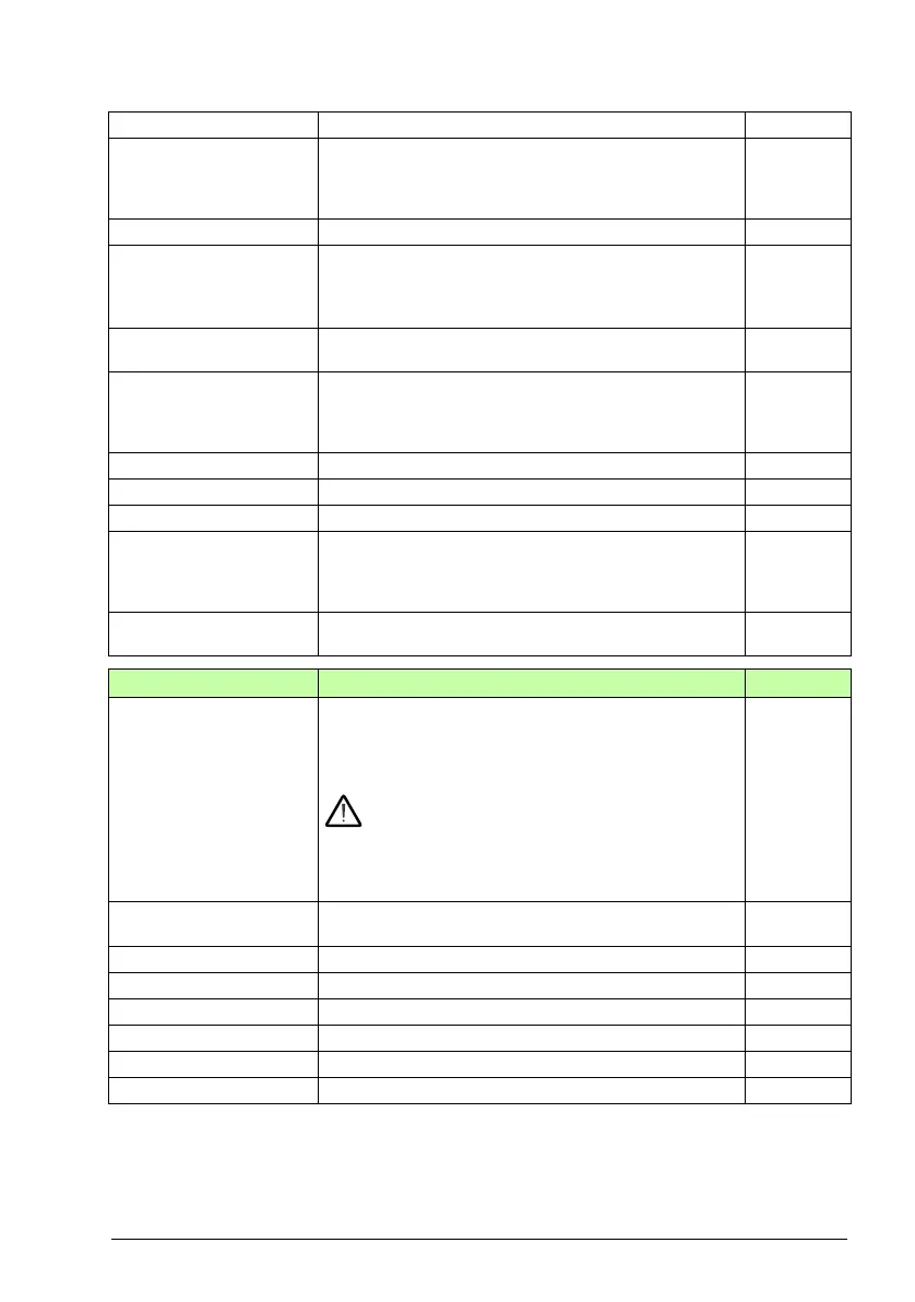
95.01 Supply voltage Selects the supply voltage range. This parameter is used by
the drive to determine the nominal voltage of the supply
network. The parameter also affects the current ratings and
the DC voltage control functions (trip and brake chopper
activation limits) of the drive.
WARNING! An incorrect setting may cause the motor
to rush uncontrollably, or the brake chopper or resistor
to overload.
Note: The selections shown depend on the hardware of the
drive. If only one voltage range is valid for the drive in
question, it is selected by default.
-
Not given No voltage range selected. The drive will not start modulating
before a range is selected.
0
208…240 V 208…240 V 1
380…415 V 380…415 V 2
440…480 V 440…480 V 3
500 V 500 V 4
525…600 V 525…600 V 5
660…690 V 660…690 V 6
No. Name/Value Description Def/FbEq16
 Loading...


