Fieldbus control through the embedded fieldbus interface (EFB) 613
Basics of the embedded fieldbus interface
The cyclic communication between a fieldbus system and the drive consists of 16-bit
data words or 32-bit data words (with the transparent control profiles).
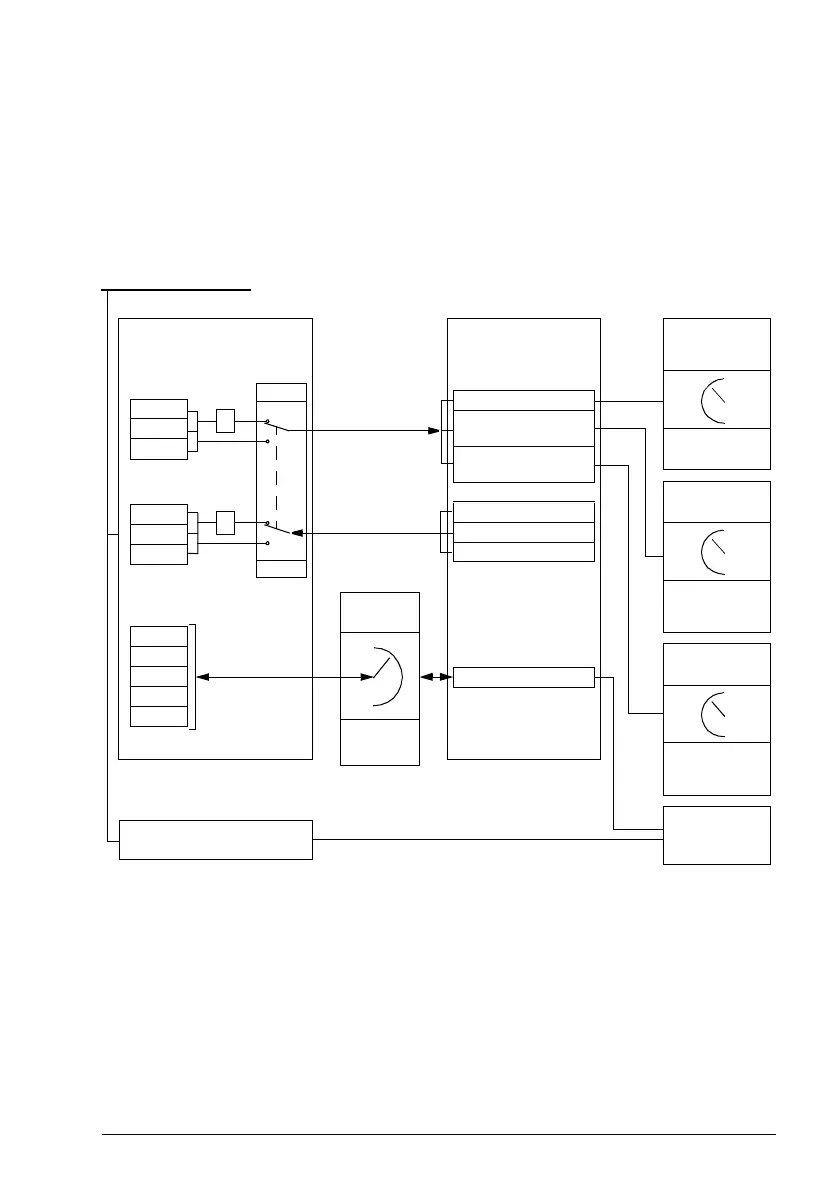
The diagram below illustrates the operation of the embedded fieldbus interface. The
signals transferred in the cyclic communication are explained further below the
diagram.
CW
REF1
REF2
SW
ACT1
ACT2
I/O 1
I/O 2
I/O 3
…
I/O 24
1. See also other parameters which can be controlled through fieldbus.
2. Data conversion if parameter 58.25 Control profile is set to ABB Drives. See section About the control
profiles (page 616).
3. If parameter 58.25 Control profile is set to Transparent,
• the sources of the status word and actual values are selected by parameters 58.30…58.32 (otherwise,
actual values 1 and 2 are automatically selected according to reference type), and
• the control word is displayed by 06.05 EFB transparent control word.
1)
Fieldbus network
Data I/O
selection
EXT1/2
Start commands
20.01
20.06
Reference
selection
Groups
22/26/28/40 etc.
Cyclic communication
Acyclic communication
SEL
Parameter
table
0
2
58.25
EFB profile
Reference
selection
Groups
22/26/28/40 etc.
58.101
…
58.124
2)
0
2
2)
EFB CW
3)
03.09 EFB reference
1
03.10 EFB reference
2
EFB SW
3)
Actual 1
3)
Actual 2
3)
Par. 01.01…255.255
 Loading...


