1MAC309294-MB F Section 4
Protection functions
RER620 137
Technical Manual
4.1.3.11 Technical data
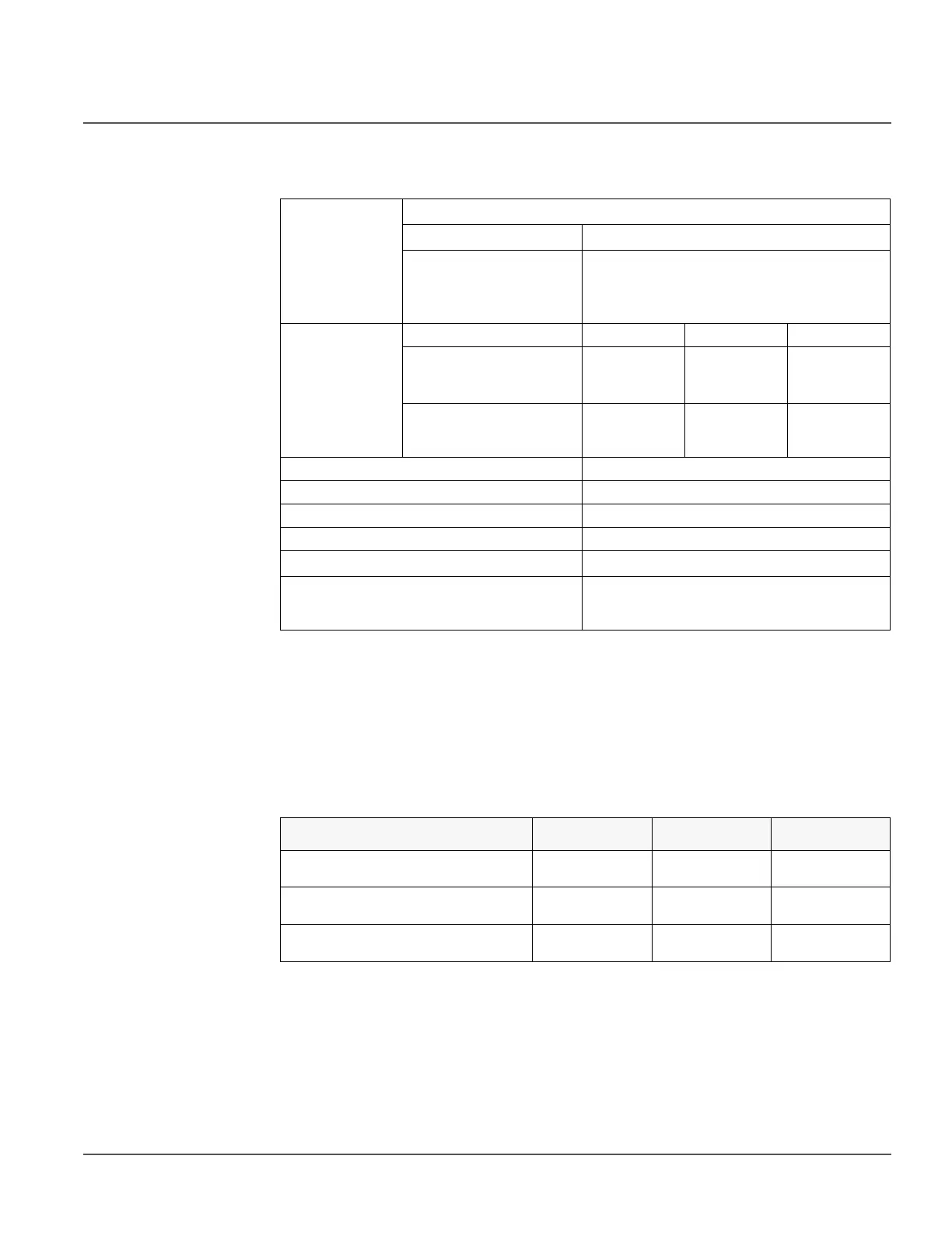
Table 161: 51N/G, 50N/G-1/2 & 50N/G-3 Technical data
4.1.4 Directional earth-fault protection 67/51N and 67/50N
4.1.4.1 Identification
Operation
accuracy
Depending on the frequency of the current measured: f
n
±2Hz
51N/G ±1.5% of the set value or ±0.002 x I
n
50N-1/2 & 50G-1/2
and
50N/G-3
±1.5% of set value or ±0.002 x I
n
(at currents in the range of 0.1…10 x I
n
)
±5.0% of the set value
(at currents in the range of 10…40 x I
n
)
Pickup time
12
1. Measurement mode = default (depends on stage), current before fault = 0.0 x I
n
, f
n
= 60 Hz, ground-fault
current with nominal frequency injected from random phase angle, results based on statistical distribution of
1000 measurements
2. Includes the delay of the signal output contact
Minimum Typical Maximum
50N/G-3:
I
Fault
= 2 x set Pickup value
I
Fault
= 10 x set Pickup value
16 ms
11 ms
19 ms
12 ms
23 ms
14 ms
50N-1/2 & 50G-1/2 and
51N/G:
I
Fault
= 2 x set Pickup value
22 ms 24 ms 25 ms
Reset time < 40 ms
Reset ratio Typical 0.96
Retardation time < 30 ms
Trip time accuracy in definite time mode ±1.0% of the set value or ±20 ms
Trip time accuracy in inverse time mode
±5.0% of the theoretical value or ±20 ms
3
3. Maximum Pickup value = 2.5 x I
n
, Pickup value multiples in range of 1.5 to 20
Suppression of harmonics RMS: No suppression
DFT: -50dB at f = n x f
n
, where n = 2, 3, 4, 5,…
Peak-to-Peak: No suppression
Function description
IEC 61850
identification
IEC 60617
identification
ANSI/IEEE C37.2
device number
Directional ground-fault protection - Low
stage 1
XDEFLPDEF1 I0>->(1) 67/51N
Directional ground-fault protection - Low
stage 2
XDEFLPDEF2 I0>->(2) 67/50N-1
Directional ground-fault protection - High
stage
XDEFHPDEF1 I0>>->(1) 67/50N-2

 Loading...


