Section 5 1MAC309294-MB F
Control functions
344 RER620
Technical Manual
In general, loop control scheme is implemented in three different configurations. These are
defined by the number of reclosers in a loop and their respective types. They are five
recloser, three recloser and four recloser configurations. The three- and five recloser
systems are basic arrangements; the four-recloser topology is a hybrid of the three- and
five-recloser topology.
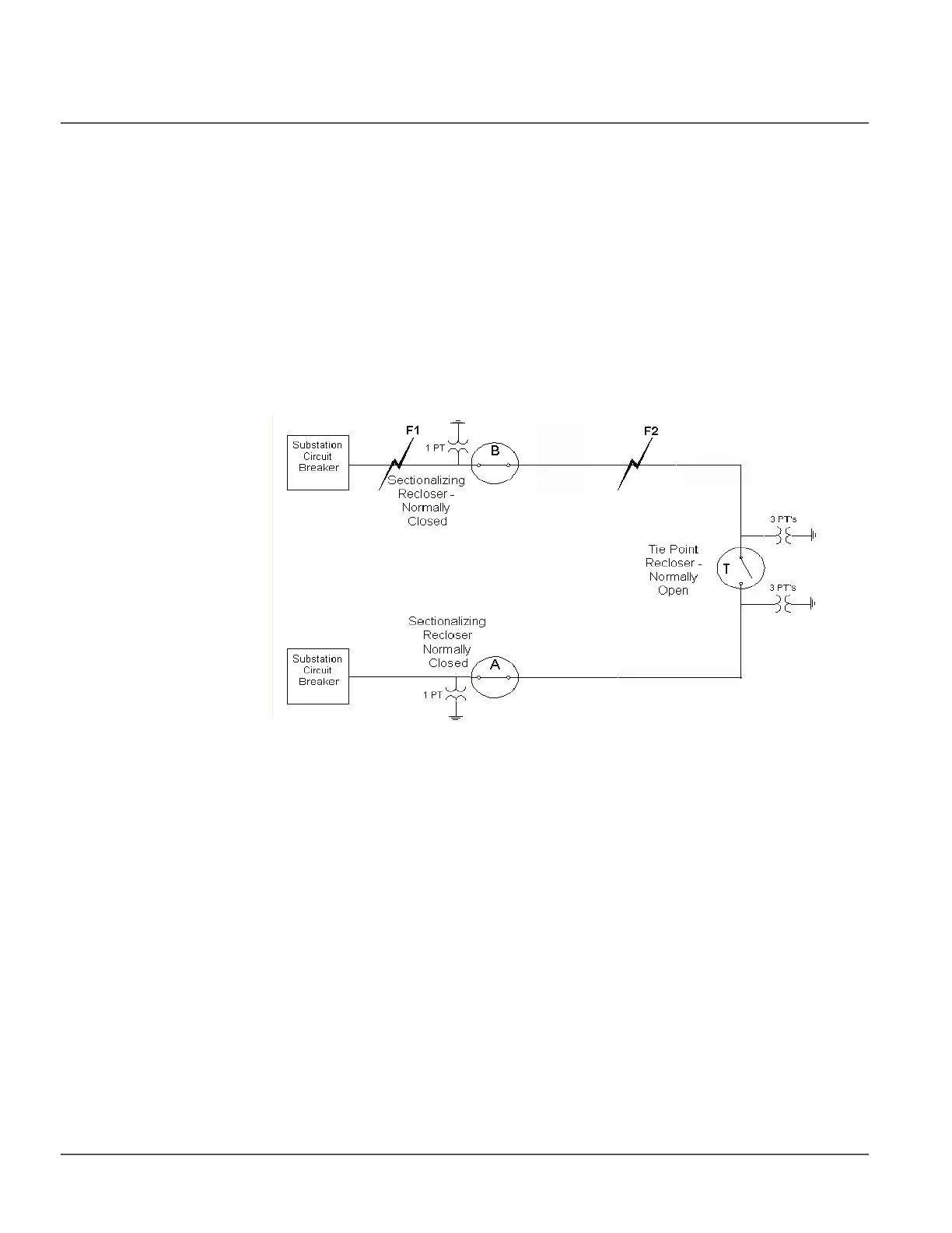
5.4.5.1 Three-Recloser Loop Control
The three-recloser system bridges two sources with a normally open TiePoint recloser.
Between each source and the TiePoint is a normally closed sectionalizing recloser. There
are two fault scenarios to consider in the three-recloser system. In one scenario, a line fault
occurs between a source and its Sectionalizing recloser. The second scenario involves a
line fault between the Sectionalizing and TiePoint recloser
Figure 182: 3-Recloser Loop Control
3-Recloser Fault 1 Scenario
In a 3-recloser loop control scheme, Figure 182, if there is a permanent fault between the
S1 circuit breaker and the sectionalizing recloser B at F1, the S1 circuit breaker will
recognize the fault and go through its reclosing shots to lockout (for illustration purposes
we will assume 3 operations to lockout for all devices). Recloser B will recognize a loss
of voltage after the first circuit breaker operation, and if the voltage does not return to
greater than live bus threshold value level for the livebus timer setting, it will automatically
trip after t1 seconds, per Figure 183, isolating the faulted zone on the source side of the
recloser. The tie-point recloser T at the same instant will recognize a loss of 3-phase
voltage on the S1 side of its recloser PTs. After a delay time of t2 seconds from the initial
fault at S1 the tie-point recloser T will close. This establishes service from S2, recloser A
and through the tie-point recloser T to the faulted sectionalizing recloser B. Figure 183 and
Table 313 summarize the events.

 Loading...


