Section 9 1MAC309294-MB F
Other functions
434 RER620
Technical Manual
9.1.7 Settings
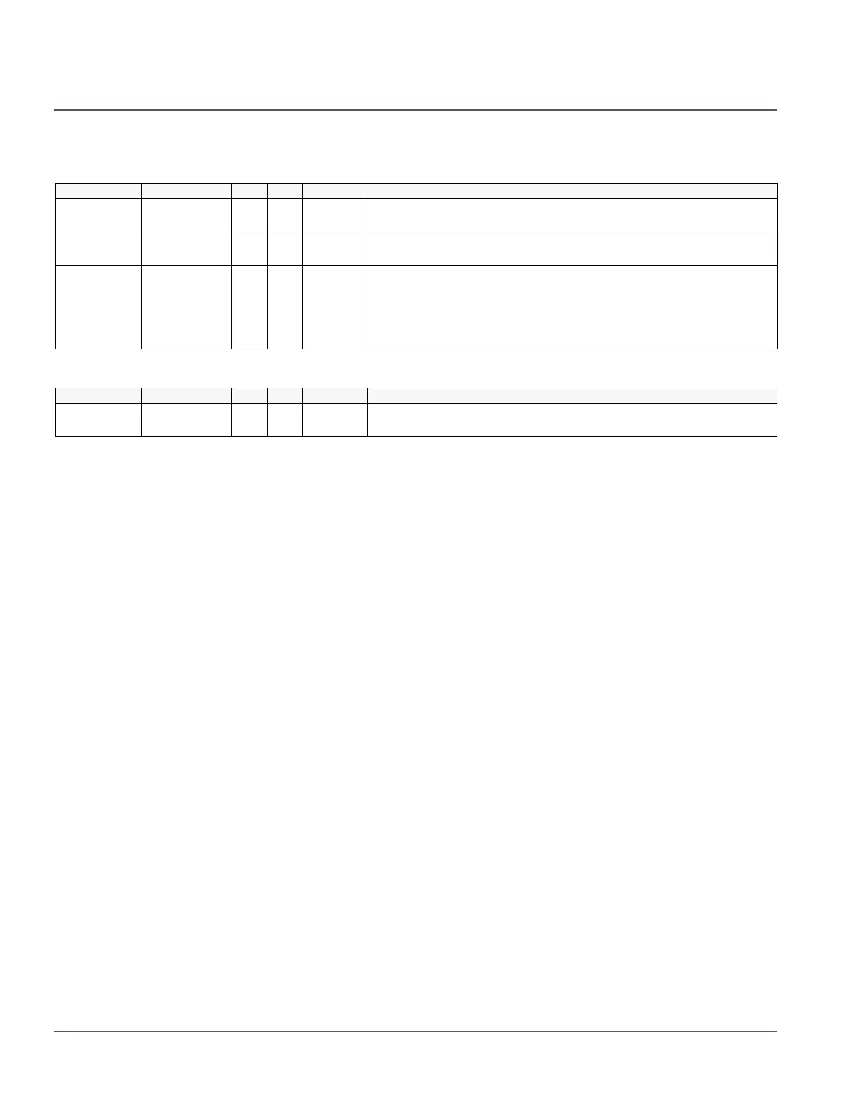
Table 388: Non-group settings for UPS
Table 389: Non-group settings for CVD clamping
Parameter Values (Range) Unit Step Default Description
Aux Mode 1 = on
0 = off
bin 1 0=off Aux supply set to on/off
Aux Voltage 1 = 24V
0 =12V
bin 1 0=12V Aux supply set to 12V or 24V
Boost Voltage 60...250 Vdc 1 240Vdc The boost voltage (also referred to as the “250Vdc rail”) is the power source for
actuator operation. The boost voltage is adjustable via communications. This
voltage is connected to the drain side of the IBGT on the UPD board. This
voltage may change with the needs of each pole type driven by the UPD. The
value is a non-signed byte. Setting the Boost voltage to 60 will switch off the
function.
Parameter Values (Range) Unit Step Default Description
CVD
clamping
1 = enable
0 = disable
bin 1 0=disable CVD Voltage Clamping

 Loading...


