Section 9 1MAC309294-MB F
Other functions
436 RER620
Technical Manual
Table 391: Monitored data for CVD clamping
9.2 Universal power drive UPD
9.2.1 Function block
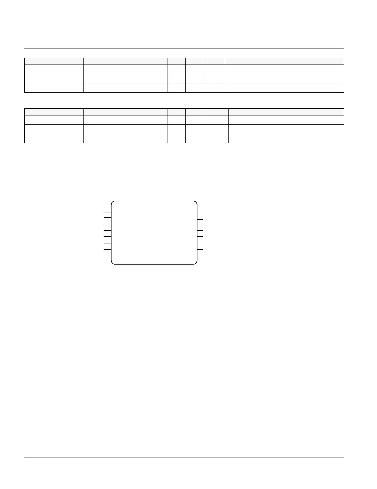
Figure 225: UPD function block
9.2.2 Functionality
The Universal Power Drive (UPD) module is designed specifically for the RER620. It is
a two-width module in Slot 2 (X115) of the RER620 case. The UPD module is a single
circuit board that provides six half-bridge drivers that are connected to form three
independent electrical full-bridge drive channels. Each channel consists of four switches
(FET/ IGBT) in a bridge arrangement. Two of the switches in each channel are high-side
and two are low-side. The purpose of each channel is to allow current flow through an
attached load to be in the forward or reverse direction. The intended load for each channel
is single coil actuator. Each actuator is mechanically connected to a vacuum bottle switch.
The actuator and vacuum bottle make up a single pole. The UPD is normally attached to
three poles for control of a three-phase feeder in an electrical distribution system.
UPS Fw Version: 00.0...99.9 ver 0.1 UPS firmware version
UPS Hw Version: 00.0...99.9 ver 0.1 UPS hardware version
UPS Bootldr Version: 00.0...99.9 ver 0.1 UPS boot-loader version
Parameter Values (Range) Unit Step Default Description
CVD_CLP_A 1=True 0=False bin 1 0=False Phase A CVD clamping Status
CVD_CLP_B 1=True 0=False bin 1 0=False Phase B CVD clamping Status
CVD_CLP_C 1=True 0=False bin 1 0=False Phase C CVD clamping Status
Parameter Values (Range) Unit Step Default Description
X115 (UPD)
OPEN_A
OPEN_B
OPEN_C
OPEN_3P
CLOSE_A
CLOSE_B
CLOSE_C
CLOSE_3P
X115-Input 1
X115-Input 2
X115-Input 3
X115-Input 4
X115-Input 5
X115-Input 6

 Loading...


