1MAC309294-MB F Section 5
Control functions
RER620 337
Technical Manual
A recloser loop control scheme typically utilizes a predetermined RER620 controlled
reclosers installed in series between two substation feeder circuits. This provides isolation
of any faulted section within a given distribution circuit while re-establishing service to all
customers unaffected by the faulted section within a relatively short period. Loop control
schemes are typically located at or near key customers at various locations throughout the
distribution system, or where reliability on particular circuits is particularly poor.
There are three common configurations that the loop control can be configured. These are
defined by the number of reclosers in a loop and their respective types. The three- and five
recloser systems are basic arrangements; the four-recloser topology is a hybrid of the
three- and five-recloser topology.
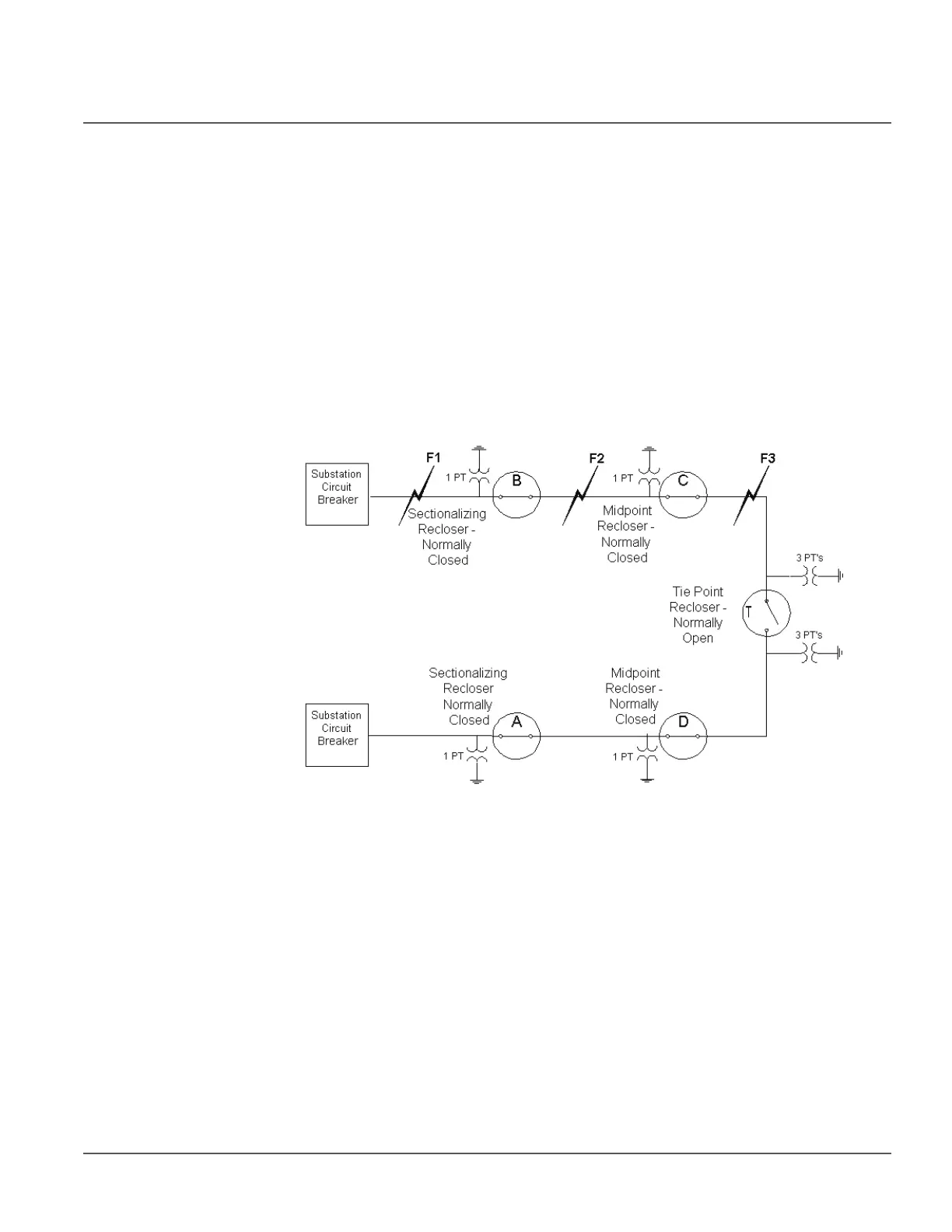
The distribution one-line diagram in Figure 178 represents a typical full implementation
of a loop system.
Figure 178: 5-Recloser loop control system
A typical full implementation of a loop system consists of 3 type of reclosers:
• Sectionalizing reclosers
• Midpoint reclosers
• TiePoint recloser
An explanation of the function of each of these reclosers types is given in the section
below.
5.4.3.1 Sectionalizing Recloser
The Sectionalizing recloser is a normally closed recloser that opens in response to a
downstream fault condition or to a loss of phase voltage from an upstream circuit. The
sectionalizer is typically the first protective device on the distribution line outside the
substation. Various settings determine the Sectionalizing recloser's sensitivity to both
current and voltage conditions. By design, for permanent faults between the substation and

 Loading...


