1MAC309294-MB F Section 11
Requirements for measurement transformers
RER620 551
Technical Manual
Delay in operation caused by saturation of current transformers
The saturation of CT may cause a delayed relay operation. To ensure the time selectivity,
the delay must be taken into account when setting the trip times of successive relays.
With definite time mode of operation, the saturation of CT may cause a delay that is as
long as the time constant of the DC component of the fault current, when the current is only
slightly higher than the pickup current. This depends on the accuracy limit factor of the
CT, on the remanence flux of the core of the CT, and on the trip time setting.
With inverse time mode of operation, the delay should always be considered as being as
long as the time constant of the DC component.
With inverse time mode of operation and when the high-set stages are not used, the AC
component of the fault current should not saturate the CT less than 20 times the pickup
current. Otherwise, the inverse operation time can be further prolonged. Therefore, the
accuracy limit factor F
a
should be chosen using the formula:
F
a
> 20*Current pickup value / I
1n
The Current pickup value is the primary pickup current setting of the relay.
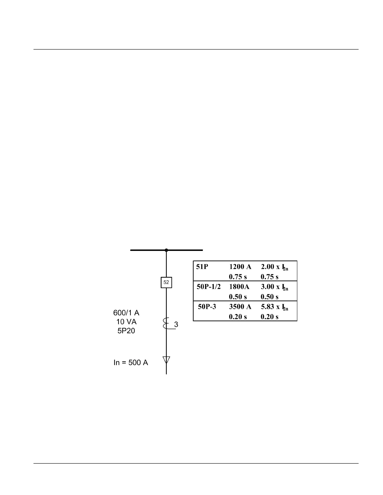
11.1.1.3 Example for non-directional overcurrent protection
The following figure describes a typical medium voltage feeder. The protection is
implemented as three-stage definite time non-directional overcurrent protection.
Figure 312: Example of three-stage overcurrent protection
The maximum three-phase fault current is 41.7 kA and the minimum three-phase short
circuit current is 22.8 kA. The actual accuracy limit factor of the CT is calculated to be 59.
The pickup current setting for low-set stage (51P) is selected to be about twice the nominal
current of the cable. The trip time is selected so that it is selective with the next relay (not
visible in the figure above). The settings for the high-set stage and instantaneous stage are
defined also so that grading is ensured with the downstream protection. In addition, the
pickup current settings have to be defined so that the relay operates with the minimum fault

 Loading...


