Section 4 1MAC309294-MB F
Protection functions
148 RER620
Technical Manual
coil or the grounding resistor. This is the case for instance, when a directional ground-fault
relay is used in an MV-switching substation some kilometers from the HV/MV -substation
in which the grounding facilities are located. Another example is when
HV/MV-substations are connected in parallel but located far from each other.
It is easy to give the tripping sector such a width that all possible directions of the
I
0
-phasors of a faulty line are covered by one and the same sector. Thus, the problem of
setting the characteristic angle according to the grounding status of the network is easily
solved. There is no need to change any settings when a Petersen coil or a grounding resistor
is switched on or off. Auxiliary switches and other pieces of extra hardware are no longer
required for ensuring the selectivity of the directional ground-fault protection.
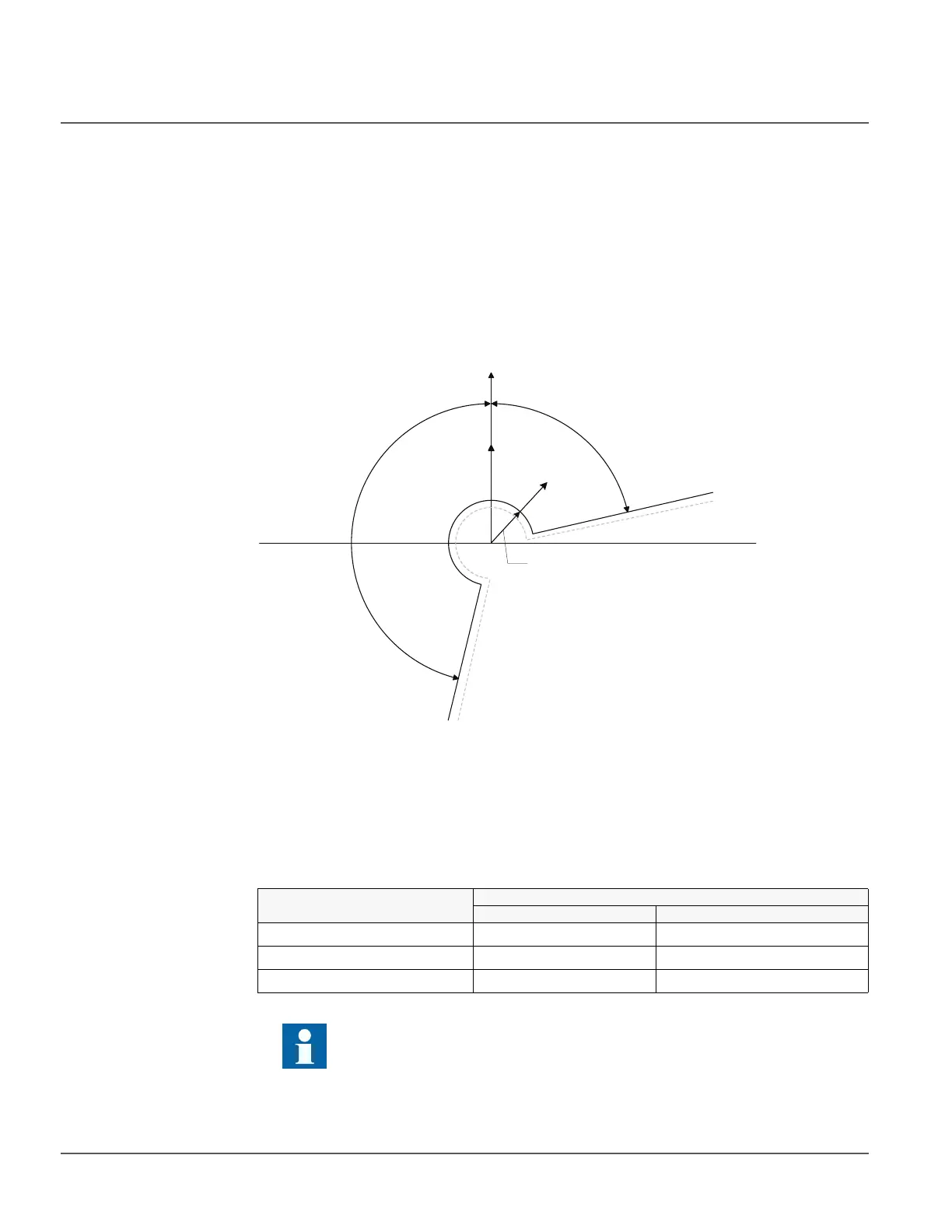
Figure 64: Extended operation area in directional ground-fault protection
4.1.4.6 Measurement modes
The function operates on three alternative measurement modes: “RMS”, “DFT” and
“Peak-to-Peak”. The measurement mode is selected with the Measurement mode setting.
Table 166: Measurement modes supported by 67/51N and 67/50N stages
Max forward angle
RCA=0°
Current start value
Positive
operation
sector
Negative
operation
sector
-
Min forward angle
0
V
0
I
Measurement mode
Supported measurement modes
67/51N and 67/50N-1 67/50N-2
RMS x x
DFT x x
Peak-to-Peak x x
For a detailed description of the measurement modes, see the General
function block features section in this manual.

 Loading...


