Section 4 1MAC309294-MB F
Protection functions
258 RER620
Technical Manual
M = Distance to point of fault from relay location
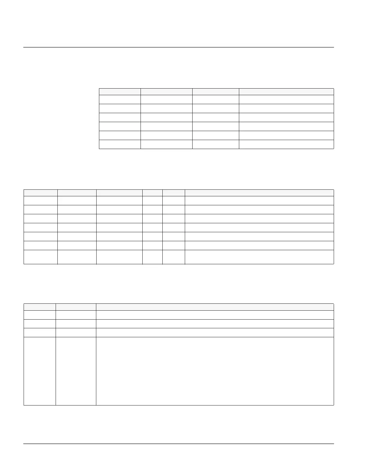
4.5.4.6 Signals
Table 269: FLO input signals
4.5.4.7 Settings
Table 270: FLO group settings
4.5.4.8 Monitored data
Table 271: FLO monitored data
Name Type Default Description
V_A SIGNAL 0 Phase A Voltage
V_B SIGNAL 0 Phase B Voltage
V_C SIGNAL 0 Phase C Voltage
I_A SIGNAL 0 Phase A Current
I_B SIGNAL 0 Phase B Current
I_C SIGNAL 0 Phase C Current
Parameter Values (Range) Unit Step Default Description
Operation ON/OFF ON Operation
Line Length 0.00…300.00 Miles/Kms 100.00 Length of the transmission or distribution line in miles
R1 0.000...20.000 Ohm/(Mile or Km) 1.000 Positive sequence resistance of line in primary Ohm/(Mile or Km)
X1 0.000...30.000 Ohm/(Mile or Km) 2.000 Positive sequence reactance of line in primary Ohm/(Mile or Km)
R0 0.000...20.000 Ohm/(Mile or Km) 0.010 Zero sequence resistance of line in primary Ohm/(Mile or Km)
X0 0.000...30.000 Ohm/(Mile or Km) 1.000 Zero sequence reactance of line in primary Ohm/(Mile or Km)
Phase Level 0.00...40.00 %In 0.10 Threshold magnitude of phase current in the per-unit of primary
rated current
Name Type Description
FLT_DIST FLOAT32 Estimated distance to fault in Miles or Kms depending on Line parameter units
FLT_R FLOAT32 Estimated fault resistance in ohms
XF_LOOP FLOAT32 Estimated reactance in the fault loop in ohms
FLT_LOOP -1=ABG Fault
-2=BCG Fault
-3=CAG Fault
-4=ABCG Fault
0=No Fault
1=AG Fault
2=BG Fault
3=CG Fault
4=AB Fault
5=BC Fault
6=CA Fault
7=ABC Fault
Fault loop

 Loading...


