motors.
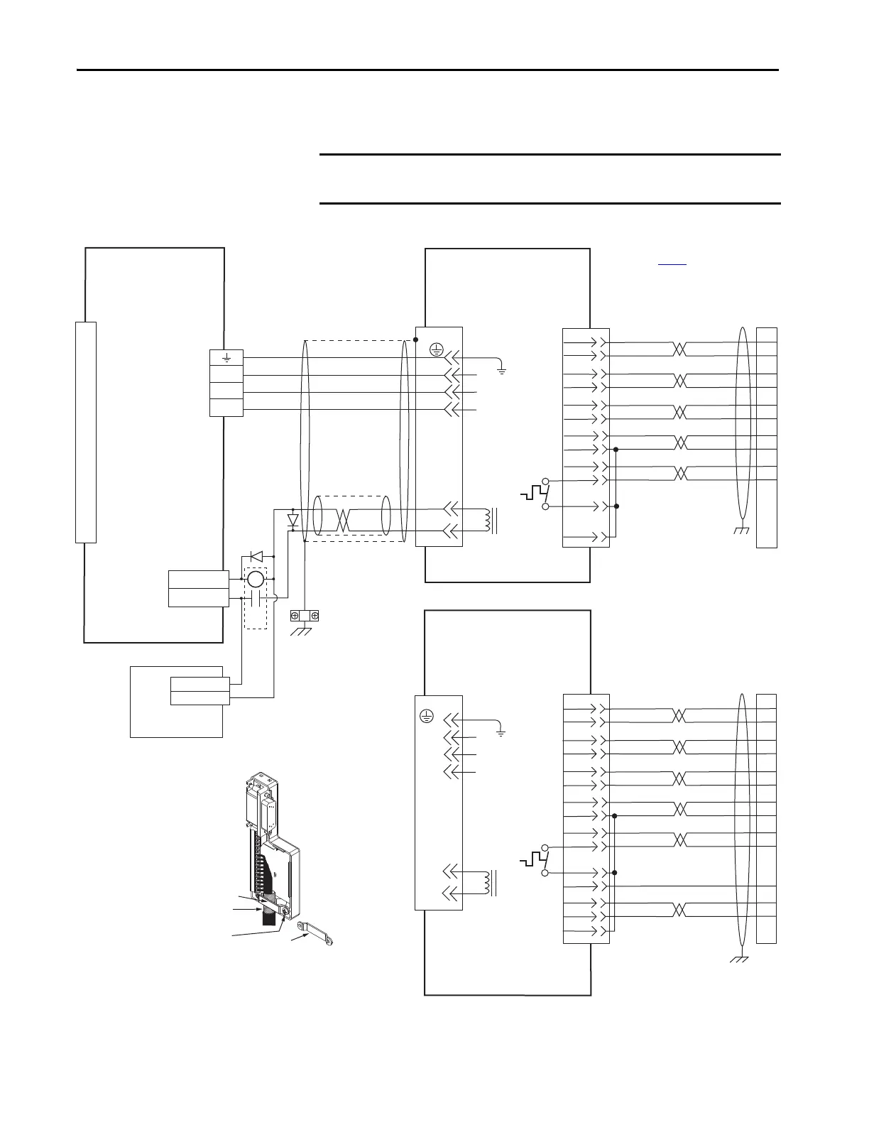
I/O (IOD)
Connector
Note 4
Motor Power
(MP) Connector
2097-V3xPRx-LM
Kinetix 350 Drives
MPL-A/B15xxx and MPL-A/B2xxx
and MPS-A/Bxxx
Servo Motors with
High-Resolution Feedback
Motor Feedback
(MF) Connector
Three-phase
Motor Power
Motor
Feedback
Thermostat
User Supplied
24V DC
Three-phase
Motor Power
Motor
Feedback
Thermostat
MPL-A/B15xx and MPL-A/B2xx
Servo Motors with
Incremental Feedback
2090-K2CK-D15M
Connector Kit
2090-K2CK-D15M
Connector Kit
See Low Profile Connector
illustration (lower left)
for proper ground technique.
See low profile connector
illustration (lower left)
for proper grounding technique.
Low Profile Connector
(2090-K2CK-D15M shown)
Ground Technique for
Feedback Cable Shield
Turn clamp over to hold
small cables secure.
Exposed shield that is secured
under clamp.
Clamp Screws (2)
Clamp
See table on page 130
for note information.
2090-XXNFMF-Sxx (standard) or
2090-CFBM4DF-CDAFxx (continuous-flex)
(flying-lead) Feedback Cable
Notes 9, 11, 12
2090-XXNFMF-Sxx (non-flex) or
2090-CFBM4DF-CDAFxx (continuous-flex)
(flying-lead) Feedback Cable
Note 9, 11
2090-XXNPMF-xxSxx (standard)
or 2090-CPBM4DF-xxAFxx
(continuous-flex)
Motor Power Cable
Notes 9, 10
Cable Shield
Clamp
Note 8
Note 13
Note 6
ORANGE
WHT/ORANGE
GRAY
WHT/GREY
GREEN
WHT/GREEN
RED
WHT/RED
BLACK
WHT/BLACK
SHIELD
GREEN/YELLOW
BLUE
BLACK
BROWN
BLACK
WHITE
GRAY
WHT/GREY
GREEN
WHT/GREEN
RED
WHT/RED
BLACK
WHT/BLACK
ORANGE
WHT/ORANGE
WHT/BLUE
YELLOW
WHT/YELLOW
Motor
Brake
Motor
Brake
Use
2090-CPWM4DF-xxAFxx
cable for continuous-flex
non-brake applications.

 Loading...


