Rockwell Automation Publication 2097-UM002D-EN-P - April 2017 79
Configure and Start up the Kinetix 350 Drive System Chapter 5
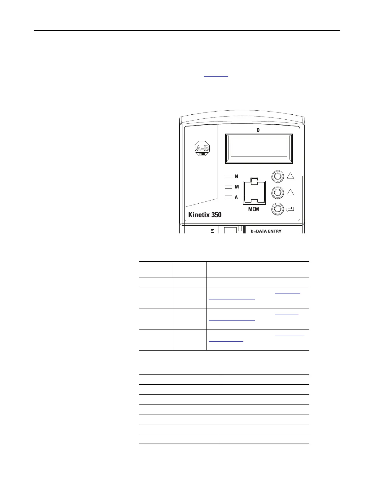
Status Indicators
The Kinetix 350 drive has four status indicators and a four-digit display on the
top front panel as shown Figure 46
. These status indicators and the display are
used to monitor the system status, activity, and troubleshoot faults.
Figure 46 - Front Panel Display
Table 37 - Status Indicators
Status
Indicator
Function Description
D Data entry Yellow status indicator flashes when changing.
N Network state
Indicates the state of the Network. See Network State
Status Indicator on page 80. The bicolored status indicator
shows red, green, or amber.
MModule state
Indicates the state of the Network. See Module State
Status Indicator on page 79. The bicolored status indicator
shows red, green, or amber.
A Axis state
Indicates the state of the Network. See Axis State Status
Indicator on page 80. The bicolored status indicator shows
red, green, or amber.
Table 38 - Module State Status Indicator
Status Indicator State
Off Power off
Flash red/green Drive self-testing
Flashing green Standby
Solid green Operational
Flashing red Major recoverable fault
Solid red Major unrecoverable fault

 Loading...


