Rockwell Automation Publication 2097-UM002D-EN-P - April 2017 141
Interconnect Diagrams Appendix A
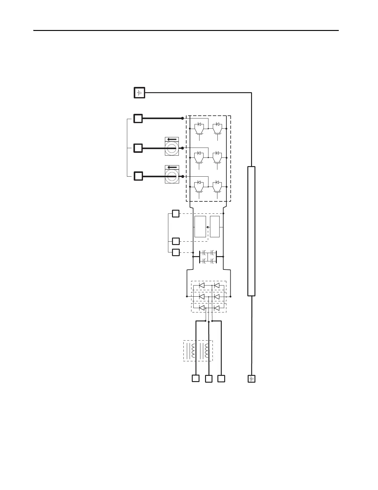
System Block Diagrams
This power block diagram applies to 2097-V32PRx-LM, 2097-V33PRx-LM,
and 2097-V34PRx-LM, servo drives.
Figure 67 - Power Block Diagram
L1
L2
L3
WV
U
Three-phase Motor Output
Inverter Section
BR
B+
Chassis
B-
DC+
2097-Rx
Shunt
Shunt
Transistor
DC-
(1)
Brake Connector
(1) The 2097-Rx shunt module is external to the Kinetix 350 drive.
L1, L2, and L3 inputs apply to
2097-V33PRx-LM and 2097-V34PRx-LM servo drives.
L1 and L2 inputs apply to
2097-V32PRx-LM servo drives.

 Loading...


