EasyManuals Logo
Home>Allen-Bradley>Servo Drives>Kinetix 350

Allen-Bradley Kinetix 350 User Manual

Allen-Bradley Kinetix 350
162 pages
To Next Page IconTo Next Page
To Previous Page IconTo Previous Page
Page #42 background imageLoading...
Page #42 background image
42 Rockwell Automation Publication 2097-UM002D-EN-P - April 2017
Chapter 3 Kinetix 350 Drive Connector Data
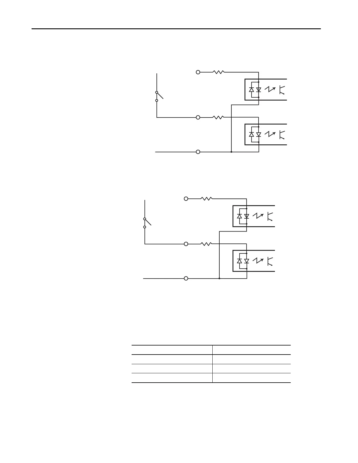
Figure 17 - Sourcing of Registration Digital Input
Figure 18 - Sinking of Registration Digital Input
Motor Brake Output
The two digital outputs (IOD-43 and IOD-44) have fixed pin assignments for
motor brake function.
The following schematic shows how to wire your motor brake.
GND
REG
REG_COM
+24V
REG
1.2 kΩ
1.2 kΩ
GND
REG
REG_COM
+24V
REG
1.2 kΩ
1.2 kΩ
Attribute Value
Circuit type Optically isolated open collector/emitter
Voltage, max 30V DC
Current, max 100 mA

Table of Contents

Questions and Answers:

Question and Answer IconNeed help?

Do you have a question about the Allen-Bradley Kinetix 350 and is the answer not in the manual?

Allen-Bradley Kinetix 350 Specifications

General IconGeneral
BrandAllen-Bradley
ModelKinetix 350
CategoryServo Drives
LanguageEnglish

Related product manuals