Rockwell Automation Publication 2097-UM002D-EN-P - April 2017 37
Kinetix 350 Drive Connector Data Chapter 3
Motor Feedback (MF) Connector Pinout
Figure 13 - Pin Orientation for 15-pin Motor Feedback (MF) Connector
Ethernet Communication Connector Pinout
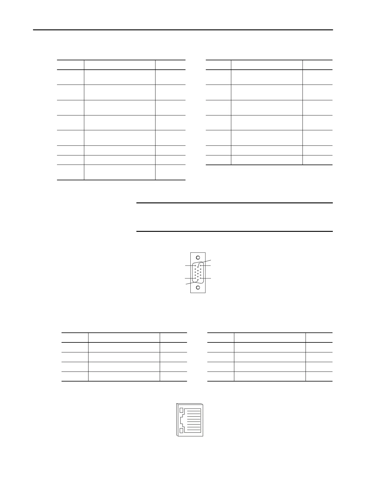
Figure 14 - Pin Orientation for 8-pin Ethernet Communication (port 1) Port
MF Pin Description Signal MF Pin Description Signal
1
Sine differential input+
AM+ differential input+
SIN+
AM+
9
Reserved
—
2
Sine differential input-
AM- differential input-
SIN-
AM-
10
Data differential input -
Index pulse-
DATA-
IM-
3
Cosine differential input+
BM+ differential input+
COS+
BM+
11
Motor thermal switch
(normally closed)
(1)
TS
4
Cosine differential input-
BM- differential input-
COS-
BM-
12
Single-ended 5V Hall effect
commutation
S1
5
Data differential input +
Index pulse+
DATA+
IM+
13
Single-ended 5V Hall effect
commutation
S2
6 Common ECOM 14 Encoder power (+5V) EPWR_5V
(2)
7 Encoder power (+9V) EPWR_9V
(2)
15 Reserved —
8
Single-ended 5V Hall effect
commutation
S3
(1) Not applicable unless motor has integrated thermal protection.
(2) Encoder power supply uses either 5V or 9V DC based on encoder/motor used.
IMPORTANT Drive-to-motor power and feedback cable length must not exceed 20 m
(65.6 ft). System performance was tested at these specifications and also
apply when meeting CE requirements.
Pin 11
Pin 6
Pin 15
Pin 1
Pin 10
Pin 5
Port 1 Pin Description Signal Port 1 Pin Description Signal
1 Transmit port (+) data terminal + TX 5 — —
2 Transmit port (-) data terminal - TX 6 Receive port (-) data terminal - RX
3 Receive port (+) data terminal + RX 7 — —
4— — 8— —

 Loading...


