Rockwell Automation Publication 2097-UM002D-EN-P - April 2017 43
Kinetix 350 Drive Connector Data Chapter 3
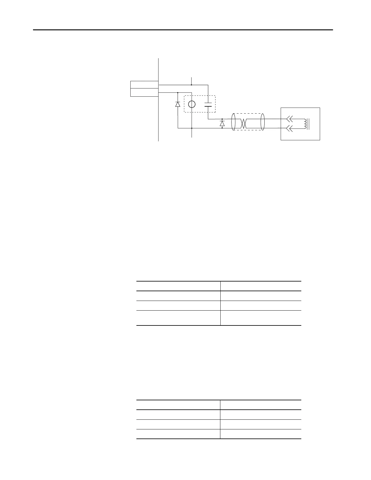
Figure 19 - Brake Wiring Schematic
Use these guidelines to wire your brake:
• Connect a diode, 1N4004, an MOV (199-MSMD1), or equivalent, as
shown, to both the relay and the motor brake coils.
• Wire the output as sourcing.
• The motor brake output is active on enable.
• Set the motor engage and disengage times that are based on the motor
selected.
Ethernet Communication Specifications
An RJ45 10 Mbit Ethernet connector (port 1) is provided on the Kinetix 350
drive. It is fully compliant to the EtherNet/IP standard. Restrict the location of
all Ethernet cabling to clean zones with minimal electromagnetic interference.
24V DC Back-up Power Specifications
The Kinetix 350 drive can use an external power supply to power the logic and
communication circuits. If an independent 24V (@ 1 A) power supply is
connected to the BP connector, the logic and communication circuits remain
active during a mains input power loss.
BR+
BR-
7
9
White
Black
CR1
MTR_BRAKE +
MTR_BRAKE -
24V DC
24V DC COM
43
44
Motor Brake
Kinetix 350 Drive
Attribute Value
Communication 100BASE-TX, full duplex
Auto MDI/MDIX crossover detection/correction Yes
Cabling
Rockwell Automation® CAT5E shielded, 100 m
(328 ft), max
Attribute Value
Input voltage 20…26V DC
Current 500 mA
Inrush, max 30 A

 Loading...


