7. Rear light
8. Right rear turn indicator
9. Speed sensor
10.STARTER MOTOR
11.Neutral sensor
12.Pick-up sensor
13.Intake air valve (MAJ2)
14.Spark plug
15.Left front turn indicator
16.Mixer oil level sensor
17.CDI control unit
18.Coolant temperature thermistor
19.Instrument panel
20.Front right turn indicator
21.Air temperature sensor
22.RAVE (Full Power) control solenoid
23.Horn
24.Throttle valve position sensor
25.Rear right turn indicator
Electrical system installation
INTRODUCTION
Scope and applicability
The purpose of this document is to define cables laying, their fastening on the motorcycle and possible
criticalities, special checks on connections and layouts, all this with the aim of obtaining vehicle relia-
bility.
Materials used and corresponding quantities
The electrical system consists of the following cable harnesses and parts:
•
1 Main Cable Harness
•
1 Front Tail Light Cable Harness
•
1 Ground lead
•
1 Cap for Magura Switches
•
1 Safety Diode
•
10 178x4 Large black clamps
•
3 98x2.5 Small black clamps
•
3 Rubber clamps
Special checks for the correct connection and laying of cables
This is the list of connectors the operator in charge of fitting must check they are correctly connected:
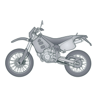
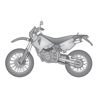
RX SX 125 Electrical system
ELE SYS - 39

 Loading...