8. Communicator Touch Panel
5
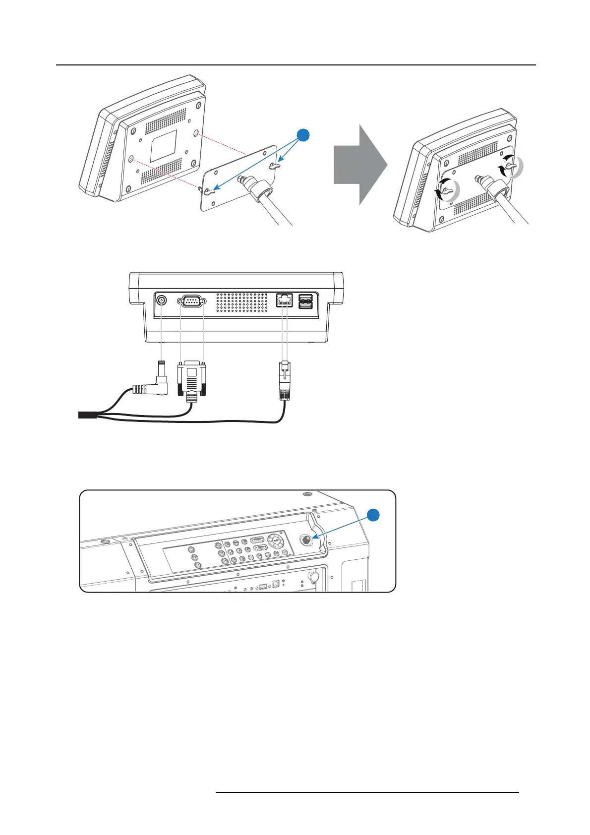
Image 8-6
4. Connect the DC plug, the RJ45 Ethernet plug and the D-SUB plug of the customized cable into t
heir respective sockets on the
Touch Panel interface.
Image 8-7
5. Connect the circular plug o f the customized cable with the circular socket (reference 6 image 8-8) at the right side of the Local
Keypad of the projector.
Caution: To avoid connector damage, align the pins before you c onnect the cus tomized cable.
Note: Ensure to tighten the locking nut on the connector.
6
Image 8-8
6. Attach the multi cable to the swivel arm us ing the two Velcro strips.
7. Position the Touch Panel interface in the desired location. See "Repositioning the Touch Panel interface", page 88.
R5906847 DP2K SLP SERIES 02/06/2017
87
 Loading...


