3-89
Confidential
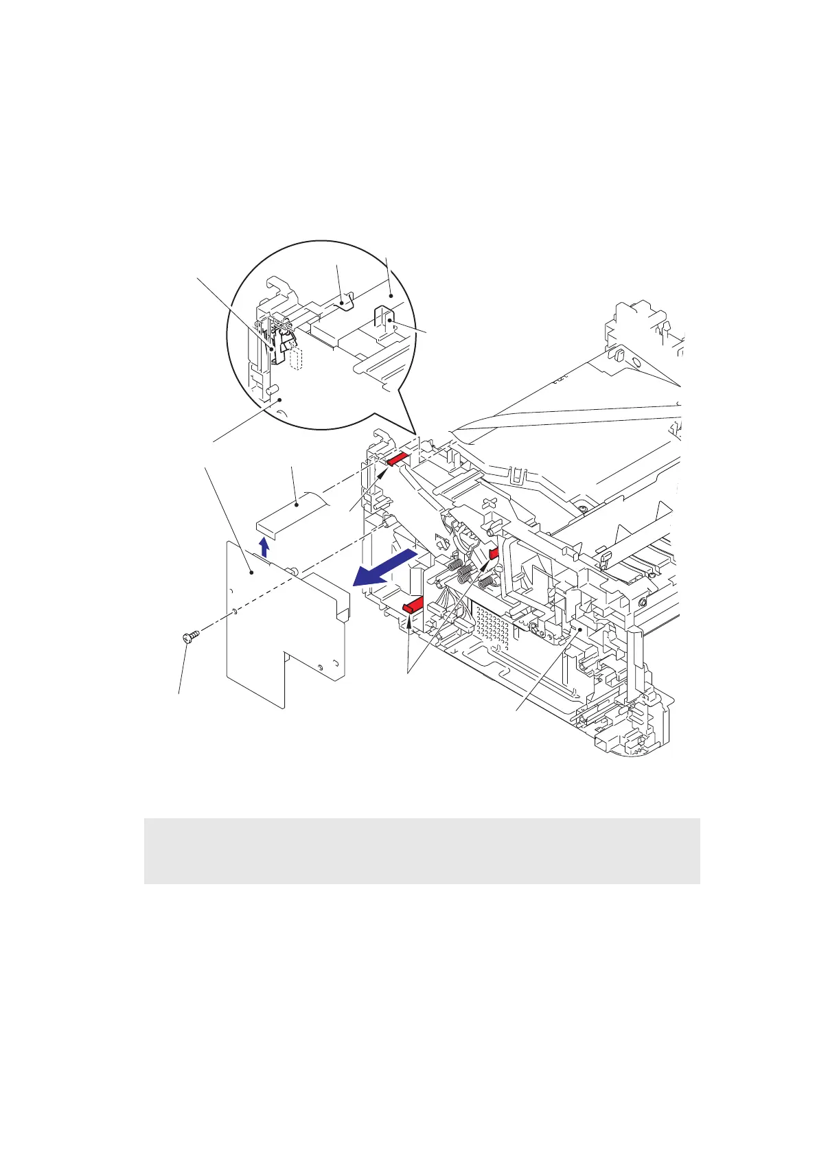
9.23 High Voltage Power Supply PCB ASSY
(1) Remove the flat cable from the guides of the main frame R ASSY, and disconnect the
connector from the high voltage power supply PCB ASSY.
(2) Remove the taptite bind B M4x12 screw.
(3) Release the hooks to remove the high voltage power supply PCB ASSY.
Fig. 3-77
Assembling Note:
• Assemble the front cover sensor lever after assembling the high voltage power supply
PCB ASSY.
Guide
Guide
Main frame R ASSY
Front cover sensor lever
Flat cable
Flat cable
High voltage power
supply PCB ASSY
Hook
Hooks
Taptite bind B M4x12
 Loading...