3-107
Confidential
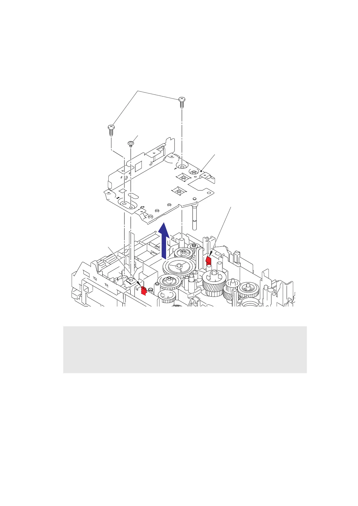
9.36 Paper Eject Sensor PCB ASSY
(1) Remove the taptite cup S M3x6 SR screw and the two taptite bind B M4x12 screws.
(2) Release the hooks to remove the main PCB shield.
Fig. 3-96
Assembling Note:
• When assembling the main PCB shield, insert the flat cable of the paper eject sensor
PCB ASSY into the hole of the main PCB shield.
• When assembling the main PCB shield, tighten the two taptite bind B M4x12 screws in
numerical order written in the plate.
1
2
Main PCB shield
Hook
Hook
Taptite bind B M4x12
Taptite cup S M3X6 SR
 Loading...