3-90
Confidential
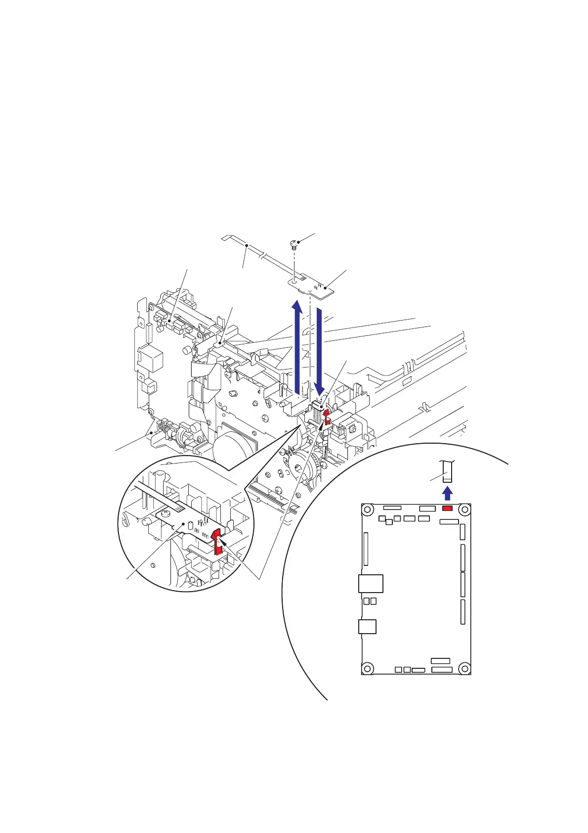
9.24 New Toner Sensor PCB ASSY
(1) Rotate the machine 180° to the side of main frame L ASSY.
(2) Disconnect the flat cable of the new toner sensor PCB ASSY from the main PCB ASSY,
and remove the flat cable of the new toner sensor PCB ASSY from the guide of the main
frame L ASSY.
(3) Remove the taptite bind B M3x10 screw.
(4) Release the hooks to remove the new toner sensor PCB ASSY.
(5) Disconnect the connector from the bottom side of the new toner sensor PCB ASSY.
Fig. 3-78
Harness routing: Refer to “4. New toner sensor PCB ASSY”.
Main PCB ASSY
CN16
Flat cable
(New toner sensor PCB ASSY)
New toner sensor PCB ASSY
New toner sensor
PCB ASSY
Flat cable
Main PCB ASSY
Guide
Connector
Main frame L ASSY
Hook
Taptite bind B M3x10
 Loading...