SECTION : 4B
MASTER CYLINDER
CAUTION : Disconnect the negative battery cable before removing or installing any electrical unit or when a tool
or equipment could easily come in contact with exposed electrical terminals. Disconnecting this cable will help
prevent personal injury and damage to the vehicle. The ignition must also be in LOCK unless otherwise noted.
TABLE OF CONTENTS
SPECIFICATIONS 4B–1. . . . . . . . . . . . . . . . . . . . . . . . . .
FASTENER TIGHTENING SPECIFICATIONS 4B–1.
DIAGNOSIS 4B–1. . . . . . . . . . . . . . . . . . . . . . . . . . . . . . . .
CHECKING BRAKE PROPORTIONING VALVE 4B–1
MAINTENANCE AND REPAIR 4B–3. . . . . . . . . . . . . . .
ON–VEHICLE SERVICE 4B–3. . . . . . . . . . . . . . . . . . . . .
MASTER CYLINDER ASSEMBLY 4B–3. . . . . . . . . . .
BRAKE FLUID RESERVOIR 4B–5. . . . . . . . . . . . . . . .
PROPORTIONING VALVE 4B–7. . . . . . . . . . . . . . . . . .
UNIT REPAIR 4B–8. . . . . . . . . . . . . . . . . . . . . . . . . . . . . .
MASTER CYLINDER OVERHAUL 4B–8. . . . . . . . . . .
GENERAL DESCRIPTION AND SYSTEM
OPERATION 4B–11. . . . . . . . . . . . . . . . . . . . . . . . . . . . .
MASTER CYLINDER 4B–11. . . . . . . . . . . . . . . . . . . . .
PROPORTIONING VALVE 4B–11. . . . . . . . . . . . . . . . .
FLUID LEVEL SENSOR 4B–11. . . . . . . . . . . . . . . . . . .
SPECIFICATIONS
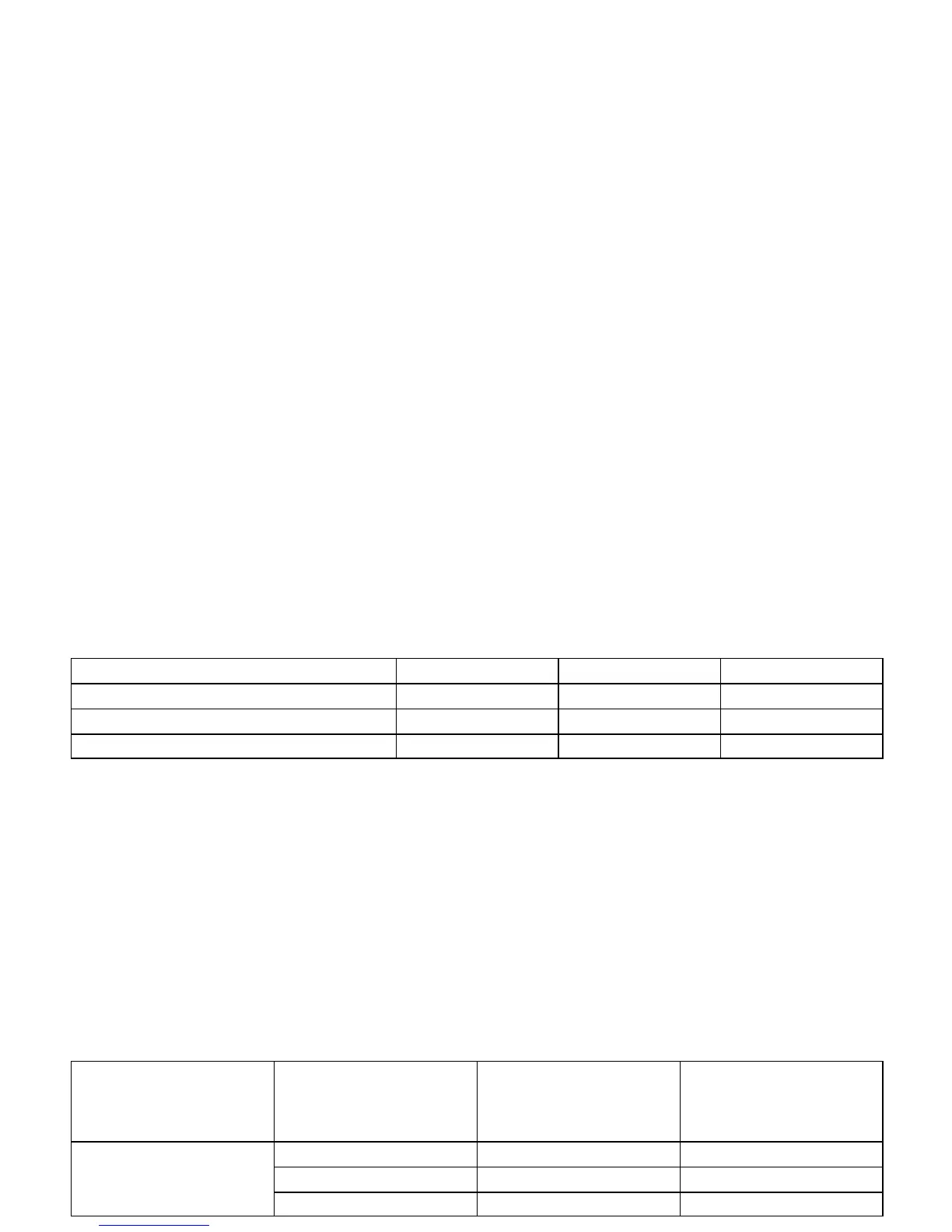
FASTENER TIGHTENING SPECIFICATIONS
Application NSm Lb–Ft Lb–In
Brake Lines 16 12 –
Master Cylinder Attaching Nuts 18 13 –
Proportioning Valves 22 16 –
DIAGNOSIS
CHECKING BRAKE
PROPORTIONING VALVE
Use two brake pressure gauges to check the brake pro-
portioning valves that are attached to the master cylinder
on non–ABS braking systems. These valves limit the out-
let pressure to the rear brakes after a predetermined mas-
ter cylinder pressure has been reached. (On ABS braking
systems, the hydraulic modulator/ motor pack assembly
controls the hydraulic pressure to both the rear wheel cyl-
inders or rear calipers, and the front calipers.)
When checking the brake proportioning valves, be sure
that the hydraulic line pressure is measured simulta-
neously and diagonally on the front and the rear axles. To
measure the pressure, use the following steps.
1. Remove the bleeder valve and install a pressure
gauge to one of the rear brake cylinders.
2. Install another bleeder valve and install another
pressure gauge to the diagonally opposite front
brake.
3. Build pressure by pressing firmly on the brake ped-
al several times. (The pressure indicated on the
gauge is not regulated and represents the actual
brake system hydraulic pressure.)
4. Build pressure until the test values in the following
proportioning valve test chart are achieved.
Engine Reference Number for
Gradient and Switching
Pressure on the Valve
Housing
Input Pressure Read on
the Manometer at the
Front Axle in kPa (psi)
Output Pressure Read
on the Manometer at the
Front Axle in kPa (psi)
2.0L 0.3/40 500 (73) 500 (73)
5 500 (798) 4 450 ± 200 (645 ± 29)
10 000 (1,450) 5 800 ± 300 (841 ± 44)

 Loading...