1C – 74IDOHC ENGINE MECHANICAL
DAEWOO V–121 BL4
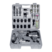
Valve Seat – Cut
1. Place the cylinder head on wooden blocks.
2. Cut the intake and the exhaust valve seats using
the guide drift KM–340–7 as follows:
S Valve seat – A 45–degree surface using the cut-
ter KM–340–13.
S Upper correction angle – A 30–degree surface
using the cutter KM–340–13.
S Lower correction angle – A 60–degree surface
using the cutter KM–340–26.
3. Clean the chippings from the cylinder head.
4. Inspect the dimension for the valve seat width.
S Intake: 1.2 to 1.4 mm (0.047 to 0.055 inch).
S Exhaust: 1.4 to 1.8 mm (0.055 to 0.070 inch).
5. Inspect the assembly height of the intake valves
and the exhaust valves. If the dimension is exceed-
ed, install new valves. Inspect the assembly height
of the intake valves and the exhaust valves again. If
the valve assembly height is still too large despite
replacing the valves, replace the cylinder head.
Assembly Procedure
1. Coat the valve stems with engine oil.
2. Insert the valves in the cylinder head in their origi-
nal positions.
3. Insert the valve spring seats.
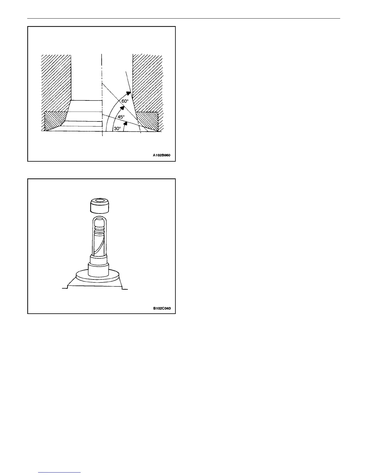
4. Push the accompanying assembly sleeve onto the
valve stem.
5. Insert the new valve stem seat.
6. Carefully drive the valve stem seal onto the stop
with light taps.
7. Install the valve springs in their original positions.
8. Install the valve spring caps.

 Loading...