Description Page
Fuel Level Sensor Procedures
3 of 7
August, 2001
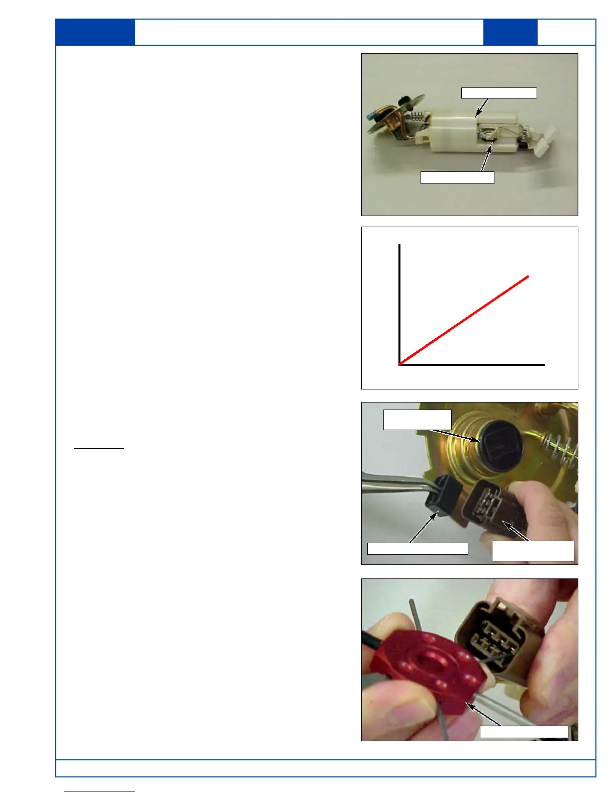
21.Slowly move the Fuel Level Sensor Float Arm
from the “empty” position to the “full” position
while observing the Fuel Level Sensor voltage
indications on the Scan Tool EVAP Data
Screen.
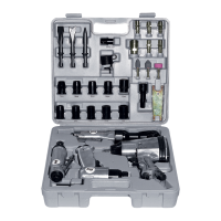
22.Confirm that the voltage makes a smooth
transition from 0.7 to 2.7 volts.
23.If the voltage "dips" or "spikes," at any point
throughout the voltage range, replace the Fuel
Level Sensor.
18.Reconnect the Wiring Harness Electrical
Connector to the Fuel Pump Module.
19.Turn the Ignition Switch to the "ON" position.
20.Connect the Scan 100 Scan Tool to the
vehicle Data-Link Connector (DLC) and go to
the EVAP Data Screen to view the Fuel Level
Sensor voltage
Screen Navigation Order:
Select “Diagnostic” 8 Choose “model year” 8
Choose “vehicle type” 8 Select “Powertrain”
8 Choose “transmission type” 8 Select “Data
Display” 8 Select “Engine Data” 8 Select
“EVAP Data”).
FUEL LEVEL SENSOR REPLACEMENT
PROCEDURE:
Removal
1. The Fuel Pump Module has a single (in-tank)
sub-harness that must be disconnected from
the Fuel Pump Module Mounting Flange
Connector.
2. Using a small pair of needle-nosed pliers,
remove and retain the secondary terminal lock
from the sub-harness electrical connector.
3. Using a suitable terminal release tool (similar to
Snap-on #YA500GM), depress the lock tang for
terminals 1 and 6, then pull the terminals out
through the back of the connector.
Note: The Fuel Level Sensor Terminals have
a beveled edge which requires proper
orientation when reinstalling in the
connector. Carefully note their
location by wire color in the connector
prior to removal.
Volts
EmptyFull
0.7
2.7
Note: Voltage sweep
should be steady with
no “dips” or “spikes”.
Fuel Level Sensor
Fuel Pump Module
Mounting Flange
Connector
Terminal Release Tool
Sub-Harness
Electrical Connector
Secondary Terminal Lock