1C – 68IDOHC ENGINE MECHANICAL
DAEWOO V–121 BL4
UNIT REPAIR
CYLINDER HEAD AND VALVE TRAIN
COMPONENTS
Tools Required
MKM–571–B Gauge
KM–340–0 Cutter Set
KM–340–7 Guide Drift
KM–340–13 Cutters
KM–340–26 Cutters
KM–348 Valve Spring Compressor
KM–653 Adapter
KM–805 Valve Guide Reamer
Disassembly Procedure
1. Remove the cylinder head with the intake manifold
and the exhaust manifold attached. Refer to ”Cylin-
der Head and Gasket” in this section.
2. Remove the coolant temperature sensor.
3. Remove the camshaft position sensor.
4. Remove the exhaust manifold heat shield bolts.
5. Remove the exhaust manifold heat shield.
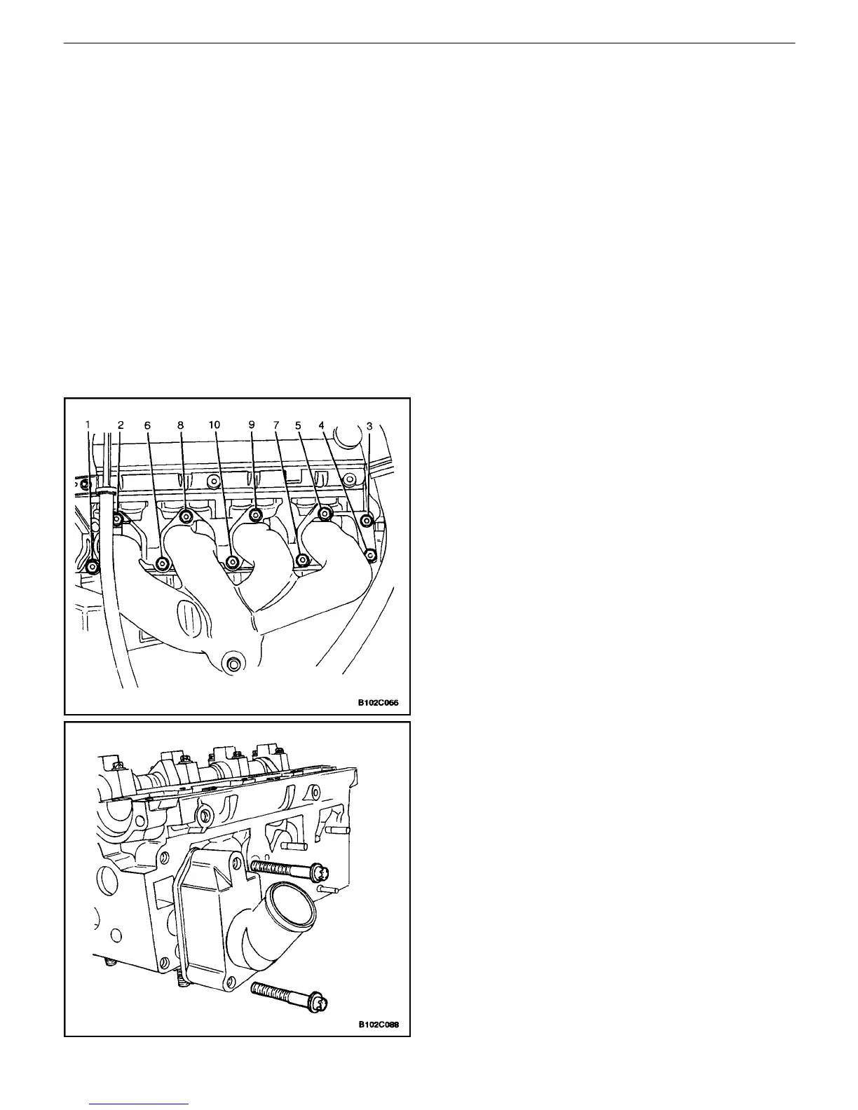
6. Remove the exhaust manifold retaining nuts in the
sequence shown.
7. Remove the exhaust manifold.
8. Remove the exhaust manifold gasket.
9. Remove the exhaust manifold studs.
10. Remove the thermostat housing mounting bolts.
11. Remove the thermostat housing assembly.
12. Remove the fuel rail assembly. Refer to Section 1F,
Engine Controls (DOHC).
13. Remove the coolant bypass housing mounting bolts
and the housing.

 Loading...