Configuring Link Aggregation 939
Operation in the Network
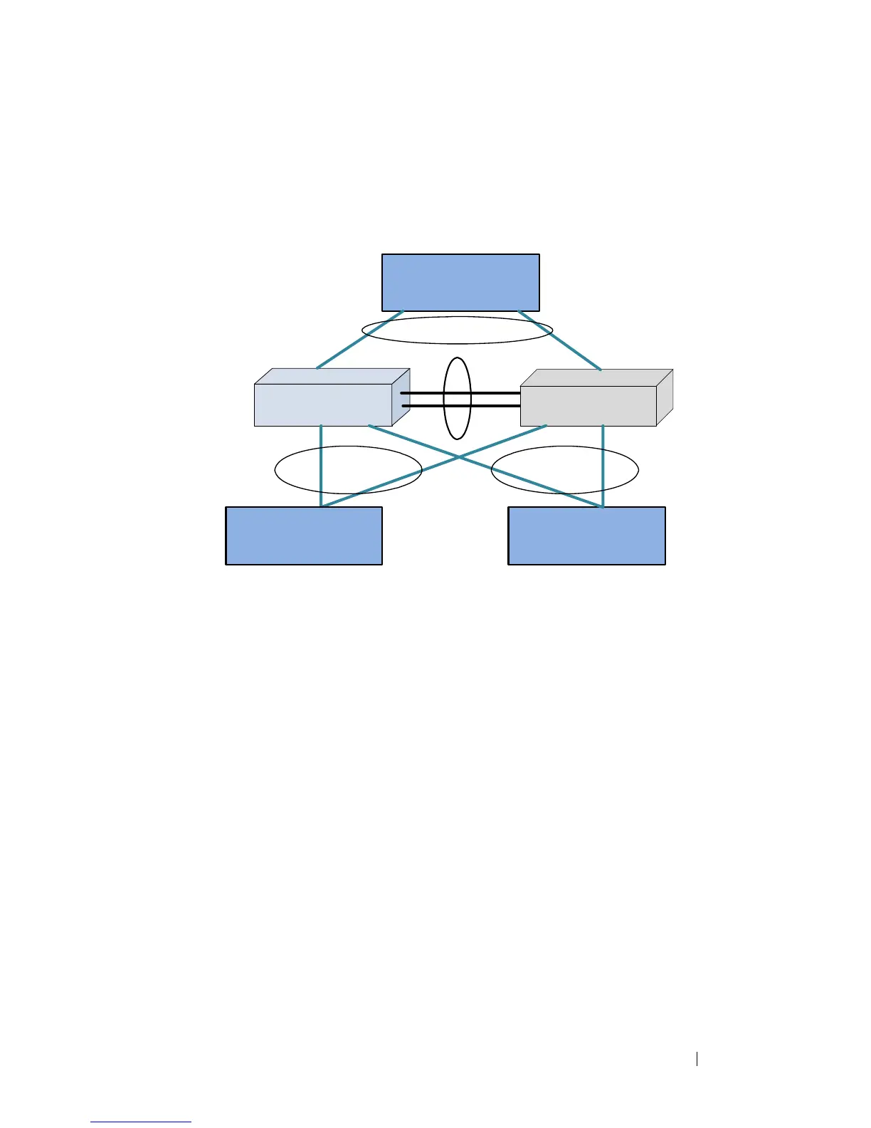
Below is a sample MLAG topology and discussion:
Figure 28-11. Example MLAG Topology
In Figure 28-11:
1
VLAN 10 spans the MLAG network.
2
P and S are MLAG-aware peer devices. P stands for primary and S stands
for secondary. The roles are elected after the DUTs exchange keep-alive
messages. The two devices are connected with a peer-link {P3/P4–S3/S4}.
Ports P1, S1 are members of MLAG1 and ports P2, S2 are members of
MLAG2.
3
A port-channel must be configured as the peer-link. In
Figure 28-11,
P3,
P4 and S3, S4 are the port-channel ports that form the peer-link.
4
MLAG devices select the roles based on keep-alive messages that run over
the peer-link.
5
A, B, and C are MLAG-unaware devices.
6
A, B, and C are partner devices that form an MLAG with P and S. On A, B,
and C, the aggregation is a regular LAG.
7
MLAG links are shown in blue.
P
S
P1
P3,P4 S3,S4
S5
P5
S1 S2P2
Peer-Link
A B
MLAG 1 MLAG 2
C
C1 C2
MLAG3
VLAN 10
 Loading...