AH Motion Controller – Operation Manual
5-2
5.1. Introduction
The chapter introduces the concept of common devices which will be used thoughout the programming process. In
addition to the common devices, to complete a more complicated program you may also need to use other elements such
as symbols, enumerations which are also introduced in this chapter. For motion control programming, there are also
specific motion control devices which can be used for setting motion axis parameters. As long as you equipped yourself
with the knowlege of devices and symbols, you are ready to use instructions for programming.
For detailed information of instructions, refer to AH Motion Controller - Standard Instructions Manual and AH Motion
Controller - Motion Control Instructions Manual.
5.2. Common Devices
This section describes the concept of values/strings and devices which include input/output/auxiliary relays, timers,
counters, and data registers.
5.2.1. Functions of Common Devices
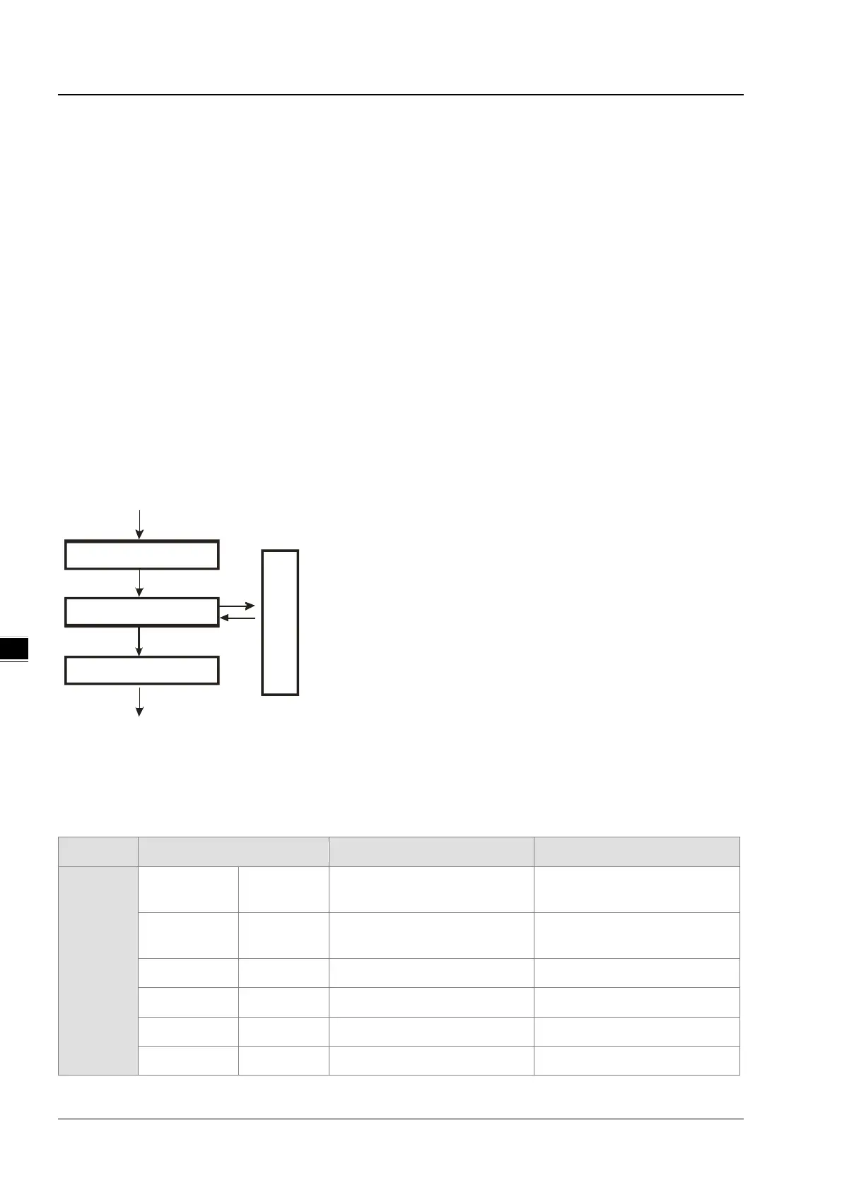
The procedure for processing the program in the PLC:
Input terminal X
Device memory
Processing the program
Device memory
Regenerating the output signal
and sending it to the output terminal
Regenerating the input signal
Device memory
Regenerating the input signal:
1. Before the progra
m is executed, the state of the external
input signal is read into the memory of the input signal.
2.
When program is executed, the state in the memory of the
input signal does not change even if the input signal
changes from ON to OFF or from OFF to ON. Not
next scan begins will the input signal be refreshed.
Processing the program:
A
fter the input signal is refreshed, the instructions in the
program are executed in order from the start address of the
program, and the results are stored in the device memories.
Regenerating the state of the output:
A
fter the instruction END is executed, the state in the device
memory is sent to the specified output terminal.
5.2.2. Device List
Type Device name Number of devices Range
Bit device
Input relay X 8192
X0.0~X511.15
(Supporting Force ON/OFF)
Output relay Y 8192
Y0.0~Y511.15
(Supporting Force ON/OFF)
Data register D 1048576 D0.0~D65535.15
Link registers
L 1048576 L0.0~ L65535.15
Auxiliary relay
M 8192 M0~M8191
Special auxiliary
SM

 Loading...

