AH Motion Controller – Operation Manual
4-46
The description of the columns in the monitoring table is as follows.
The identifier of a symbol
The name of a device monitored
If a bit device or a contact is monitored, the state will be ON or OFF.
If a symbol is monitored, the data type of the symbol will be displayed.
In the online mode, a 16-bit value is displayed.
In the online mode, a 32-bit value is displayed.
In the online mode, a 32-bit floating-point number is displayed.
You can select a format in which a value is represented.
The comments on a device or the comment on a symbol is displayed.
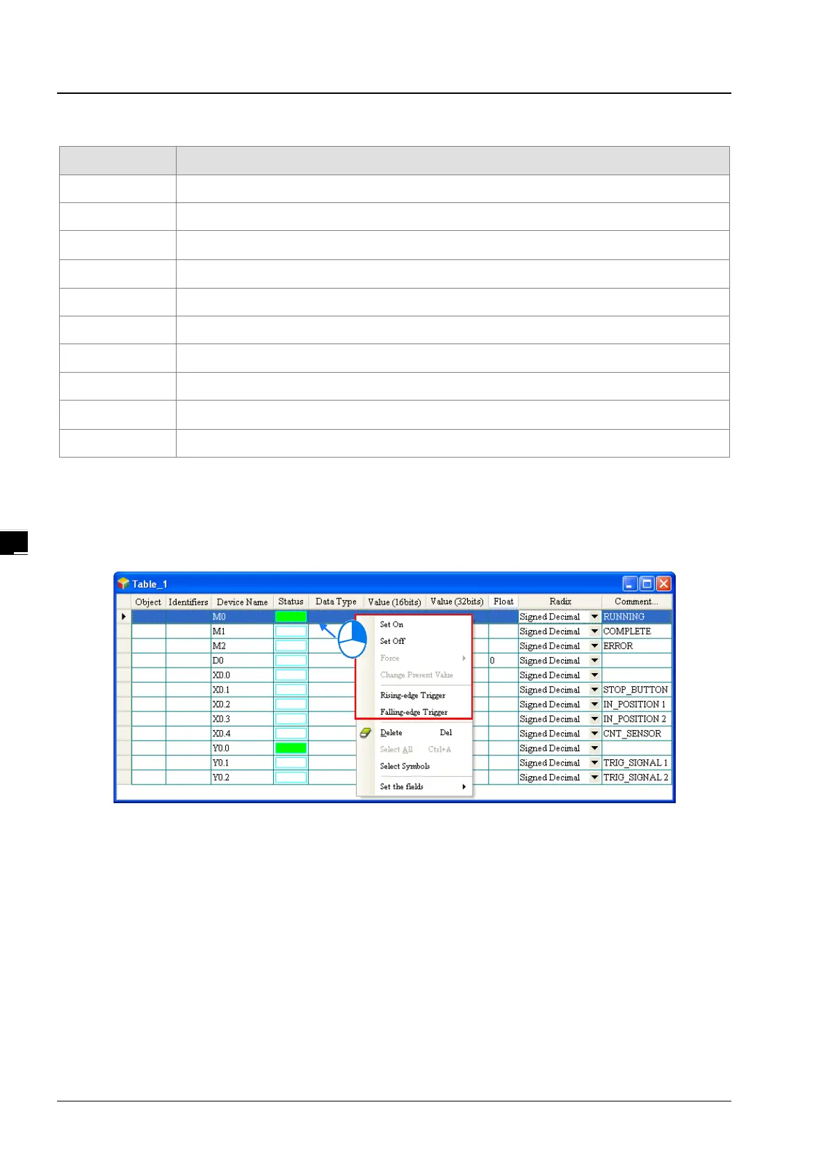
After the monitoring table is created, you can monitor the items in the monitoring table in the online mode. Besides, after
you right-click an item in the monitoring table in the online mode, a context menu which is the same as the context menu
which will after a device in the program editing window is clicked will appear. You can change the state of the item or the
value in the item by clicking an item on this context menu.
The program created in this chapter can be tested and debugged through the monitoring table created in this section.
Please refer to chapter 14 of ISPSoft User Manual for more information about testing and debugging a program.
4.6.4
Setting a Real-time Clock
The real-time clock in a PLC can be set by a tool provided by ISPSoft. Before the real-time clock in a PLC is set, you have
to make sure that ISPSoft is connected to the PLC normally. Please refer to section 3.2 for more information about
communication setting.
(1) After you click Set RTC on the Tools menu, the SET RTC window will appear. The date displayed at the top of the
window is the date retrieved from the PLC when the window is opened, and the time displayed at the top of the
window is the time retrieved from the PLC when the window is opened.

 Loading...

