EasyManua.ls Logo

Delta AH Series User Manual

Delta AH Series
288 pages
To Next Page IconTo Next Page
To Previous Page IconTo Previous Page
Page #103 background imageLoading...
Page #103 background image
Chapter 5 Understanding Common Devices
5-5
5_
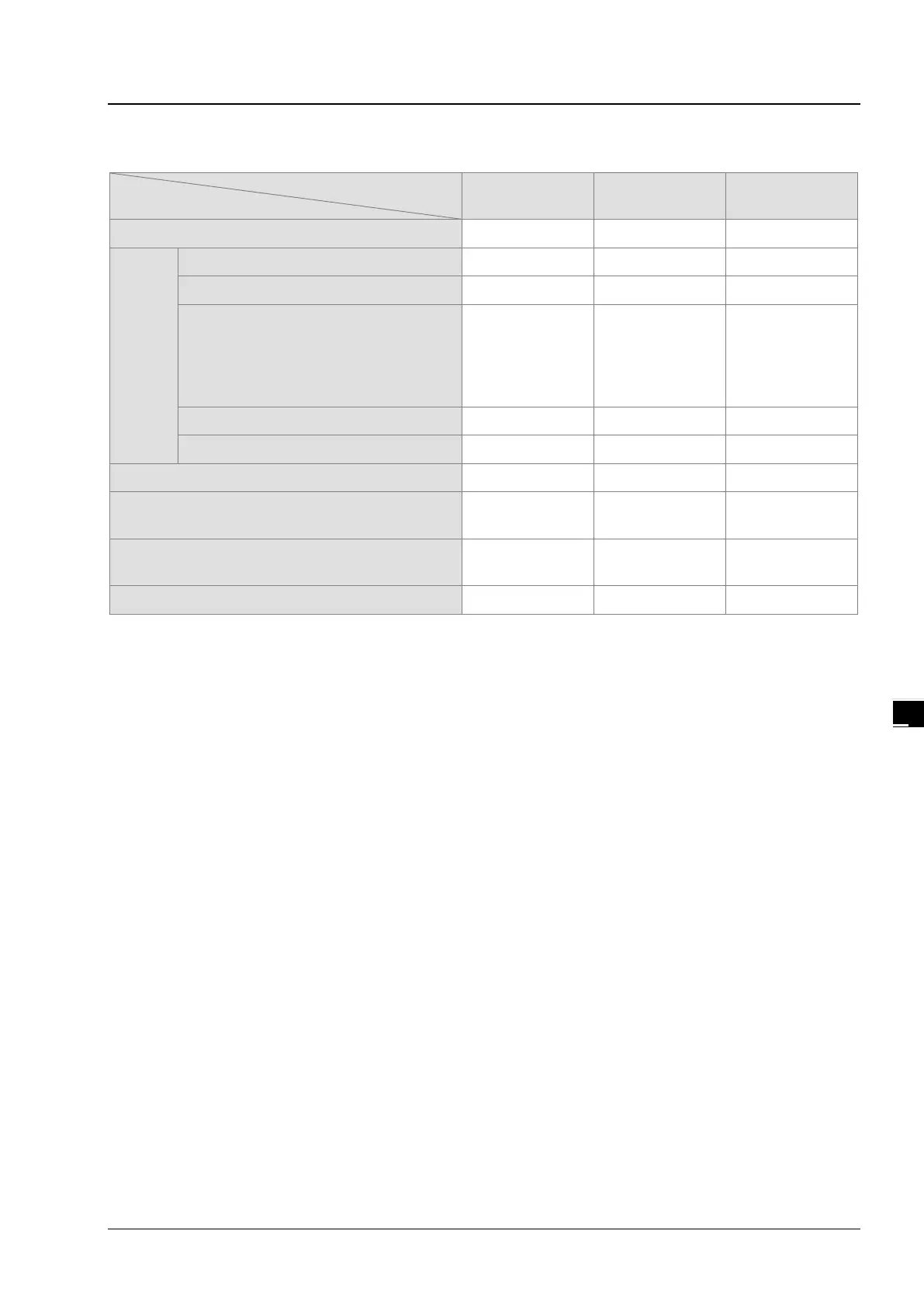
Behavior of non-latched and latched devices
Device type
PLC action
Non-latched Latched Output relay
Power: OFF
ON
Cleared
Retained
Cleared
STOP
RUN
The output relay is cleared.
Retained
Retained
Cleared
The state of the output relay is retained.
Retained
Retained
Retained
The state of the output relay returns to
that before the PLC’s stopping.
Retained Retained
The state of the
output relay
returns to that
before the PLC’s
stopping.
The non-latched devices are cleared.
Cleared Retained Cleared
The state of latched devices is retained.
Retained
Retained
Retained
RUN
STOP
Retained
Retained
Retained
SM204 is ON.
(All non-latched devices are cleared.)
Cleared Retained Cleared
SM205 is ON.
(All latched devices are cleared.)
Retained Cleared Retained
Default value
0 0 0
5.2.4. Input Relays (X)
The function of the input
The input is connected to the input device (e.g. external devices such as button switches, rotary switches, number
switches, and etc.), and the input signal is read into the PLC. Besides, contact A or contact B of the input can be used
several times in the program, and the ON/OFF state of the input varies with the ON/OFF state of the input device.
The input number (the decimal number)
For the PLC, the input numbers start from X0.0. The number of inputs varies with the number of inputs on the digital
input/output modules, and the inputs are numbered according to the order in which the digital input/output modules are
connected to the CPU module. The maximum number of inputs on the PLC can reach up to 8192, and the range is
between X0.0 and X511.15.
The input type
The inputs are classified into two types.
1. Regenerated input: Before the program is executed, the data is fed into the PLC according to the states of the
inputs which are regenerated. For example, LD X0.0.
2. Direct input: During the execution of the instructions, the data is fed into the PLC according to the states of the
inputs. For example, LD DX0.0.
5.2.5. Output Relays (Y)
The function of the output
The task of the output is sending the ON/OFF signal to drive the load connected to the output. The load can be an
external signal lamp, a digital display, or an electromagnetic valve. There are three types of outputs. They are relays,

Table of Contents

Other manuals for Delta AH Series

Question and Answer IconNeed help?

Do you have a question about the Delta AH Series and is the answer not in the manual?

Delta AH Series Specifications

General IconGeneral
SeriesAH Series
TypePLC
Programming LanguageFunction Block Diagram, Structured Text
Communication PortsEthernet, RS-232, RS-485
Power Supply24V DC

Summary

Preface

Introduction to AH Motion Controller Operation

Introduces the AH series Motion Controller CPU, system overview, programming, and troubleshooting.

Related AH Motion Controller Manuals

Lists other relevant manuals for AH Motion Controller series and AH500 series.

Navigation Between Manuals

Explains how to navigate and reference different manuals for system configuration and applications.

Chapter 1 Introduction to Motion Control Operation

Features of AH Motion

Details the advanced motion control capabilities, including PLCopen instructions and network communications.

AH Motion System Configurations

Describes the basic configurations of the AH Motion Controller series, including network and module setup.

Basic Operating Procedures for Motion Control

Outlines the fundamental steps for setting up and operating the AH Motion Control system.

Specifications of AH Motion CPU

Provides detailed environmental and general specifications for the AHxxEMC-5A series CPU.

Chapter 2 Hardware Setup

Installation Procedures

Covers the essential steps for installing the motion controller system, including CPU rack and backplane mounting.

Wiring Guidelines

Explains the connection structure and wiring for power supply and CPU modules.

Chapter 3 Software Setup

Installing and Uninstalling ISPSoft

Details the system requirements and step-by-step procedures for installing and uninstalling ISPSoft.

Installing and Uninstalling COMMGR

Provides instructions for installing and uninstalling the COMMGR software, a communication manager.

Connecting ISPSoft with AH Motion CPU

Describes the methods for connecting ISPSoft to the AH Motion Controller CPU via USB or Ethernet.

Chapter 4 Operating ISPSoft

Quick Start Example

Provides a simple example to guide users through creating a ladder diagram in ISPSoft.

Creating a Project in ISPSoft

Outlines the procedures for creating and managing projects within the ISPSoft software.

Creating a New Project

Details the steps for creating a new project, including naming and PLC type selection.

Hardware Configuration

Explains how to configure hardware components, including backplanes and modules within HWCONFIG.

Setting CPU and Module Parameters

Covers setting parameters for CPU modules and extension modules within ISPSoft's configuration windows.

Setting Module Parameters

Details parameter settings for various Analog Input/Output and Temperature Modules.

Setting PLC Parameters

Explains how to configure PLC parameters, specifically focusing on IO Input Filters.

Creating a Ladder Program

Guides users through the process of creating a traditional ladder diagram in ISPSoft.

Testing and Debugging a Program

Covers creating connections, downloading programs, and performing connection tests for debugging.

Setting a Real-time Clock

Explains how to set the real-time clock of the PLC using ISPSoft's tools.

Chapter 5 Understanding Common Devices

Introduction to Common Devices

Introduces common devices used in programming, including symbols and enumerations.

Common Devices Overview

Describes concepts of values, strings, and devices like relays, timers, and data registers.

EtherCAT Symbols

Details the EtherCAT symbols used to read states of EtherCAT slaves within ISPSoft.

Symbols and Data Types

Explains the application, classes, and data types of symbols used in PLC programming.

User-defined Data Type (ENUM)

Describes the user-defined data type for enumeration (ENUM) and its setting methods.

Chapter 6 Understanding Motion Control Devices

Motion Control Devices Overview

Introduces motion control devices used for configuring motion axis parameters in ISPSoft.

Structures Applicable for Motion Control

Details the PLCopen structures like AXIS_REF, AXES_GROUP_REF, and TRIGGER_REF.

Parameters for Motion Axes

Explains axis parameters grouped under the AXIS_REF structure for motion axis setup.

Chapter 7 Motion Control Programming

Introduction to Motion Control Programming

Explains programming concepts like Program Organization Units (POUs) and tasks related to IEC 61131-3.

Motion Control Program Architecture

Describes the program architecture and types of POUs (PROGs, FBs) within ISPSoft.

Motion Control Instructions

Lists and explains motion control instructions, including DFB and MC instructions.

Axis Configuration

Details parameters for configuring motion axes, including type, speed, and position settings.

State Transitions

Illustrates state transitions for single-axis and multi-axis motion control based on PLCopen standards.

Buffer Mode Operations

Explains the six buffer modes available for executing sequential motion instructions.

Execution of Function Block Instructions

Defines the common interface of motion control function blocks, including inputs, outputs, and timing diagrams.

Axis Positions

Describes position types and applicable positions for servo and virtual axes in motion control.

Electronic Cam Operation

Introduces electronic cam (e-cam) operations and steps for applying e-cam using software settings.

Chapter 8 Memory Cards

Overview of Memory Cards

Provides information on memory card types, appearances, and specifications, focusing on SD and SDHC.

Using a Memory Card

Explains the process of formatting a memory card for use with the AH Motion Controller CPU.

Installing and Removing a Memory Card

Details the procedure for installing and removing memory cards from the CPU's SD slot.

Memory Card Contents and Structure

Describes the initialization and default folder structure of a memory card used with the AH system.

Reading and Writing Memory Card Data

Covers backing up and restoring system data using memory cards and the CARD Utility.

CARD Utility Functions

Explains the functionalities of the CARD Utility for backup, restore, and project export operations.

System Backup Procedures

Details the step-by-step process for backing up system data to a memory card or PC.

System Restoration Procedures

Guides users through restoring system data from backup files to the CPU or ISPSoft project.

Chapter 9 Troubleshooting

Inspection and Troubleshooting

Provides basic inspection steps and procedures for identifying and resolving system errors.

Error Codes and Indicators

Lists and explains error codes, descriptions, CPU status, and LED indicator behaviors.

Troubleshooting CPU Errors

Offers corrective actions for various CPU errors indicated by ERROR and BUS FAULT LEDs.

Troubleshooting I/O Modules

Provides guidance for troubleshooting errors related to Analog I/O and Temperature Measurement Modules.

Troubleshooting Limitation Errors

Addresses software and hardware limit errors, including error codes and handling processes.

Appendices

Installing USB Driver for AH Motion CPU

Step-by-step guide for installing the USB driver for AH Motion CPU on Windows 7.

Device Addresses Overview

Lists standard Modbus and AHxxEMC device addresses for various device types.

CPU Module Operating Principles

Explains the operation, diagnosis, I/O refreshing, and communication service of the CPU module.

Related product manuals