Chapter 7 Motion Control Programming
7-23
Setting a master axis and a slave axis
Starting/Stopping an electronic cam
Creating electronic cam data (1)
Setting an input pulse type (2)
Setting a master axis (3)
Setting the starting angle of the master
axis specified (3)
Starting/Stopping a cam which
operates cyclically (3)
7.9.2.1 Initial Setting
Creating Electronic Cam Data
There are two methods of creating electronic cam data.
Method 1: Function that relates the positions of a master axis to the positions of a slave axis
Method 2: Measuring the relation between the positions of a master axis and the positions of a slave axis at work
Please refer to section 7.7.3 for more information.
Setting an Input/Output Pulse Type
1. Setting an input pulse type
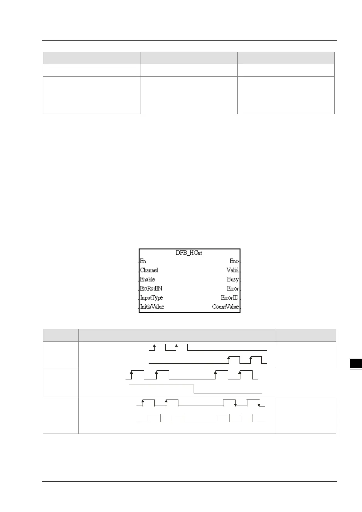
The master axis specified can be a manual pulse generator, a motion axis, AC0, AC4, AC8, AC12, AC16, or AC20. If
you use a counter as a master axis, you have to set an input pulse type. You can set an input pulse type for the
counter used by means of the motion control function block DFB_HCnt.
2. Value of InputType
Input type (positive logic)
mcUD (0)
FP Clockwise pulses
RP Counterclockwise pulses
Counting up/down
mcPD (1)
FP Pulses
RP Directions
Counterclockwise
Clockwise
Pulses+Directions
mcAB (2)
Counterclockwise
Clockwise
FP A-phase pulses
RP B-phas e pulses
A/B-phase pulses