Chapter 7 Motion Control Programming
7-7
7.4 Axis
Setting Value Unit Default
Axis Type Setting
A real axis which produces actual
output to the drive assembly
A virtual servo axis on which the
operation is done in the controller
-
Virtual servo
axis
- -
Servo Axis Form
Setting
Linear axis: The position value will be
constantly increased (or decreased)
when the linear axis rotates toward
the positive direction (or negative
direction).
Rotary axis: The position value will
be calculated again from minimum
(maximum) value after the axis which
rotates toward the positive direction
(or negative direction) reaches the
- Linear axis - -
Node Address
Setting
If Real axis is selected in the Axis
Type Setting box, the content in
Node Address Setting must be
chosen by the servo names and
station addresses in ECAT Builder. It
means that the axis is the set
EtherCAT servo drive to which the
actual output is delivered.
- 0 0 65535
Users can select a system unit. - User unit - -
Pulse Count Per
Motor Rotation
Users can set how many pulses the
controller outputs for a motor to
Pulse 10000 1 99999999
Per Motor Rotation
Users can set the distance in an
actual mechanism move whenever a
motor rotates.
User
Unit
10000 1 1000000
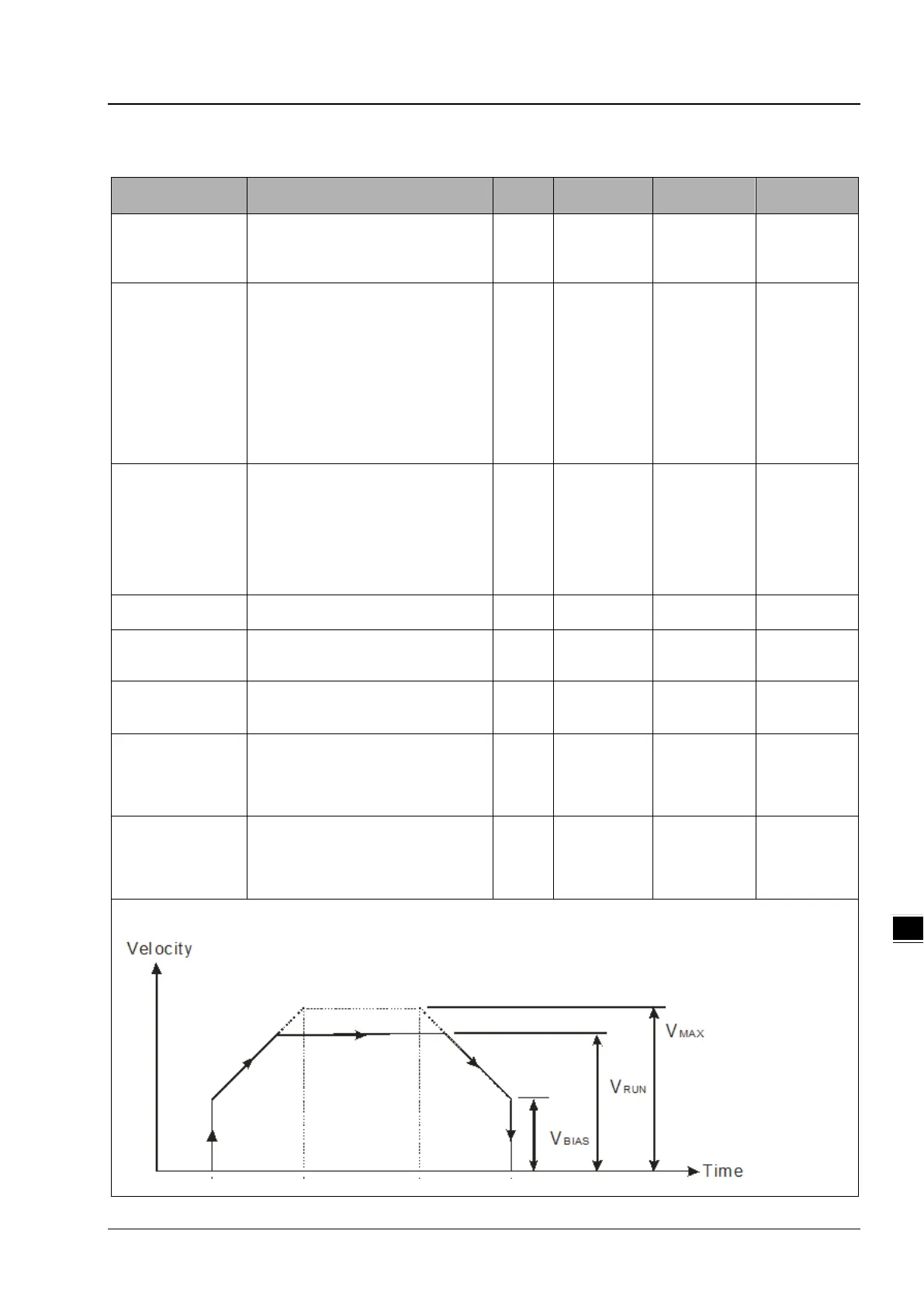
Maximum speed
setting
Users can set the upper limit of the
speed of the axis. (the program can
be refreshed by using
DFB_AxisSetting1 to input the Vmax
User
Unit/s
100000 0 2147483647
Start-up speed
setting
Users can set the start-up speed for
the axis to start running. (the
program can be refreshed by using
DFB_AxisSetting1 to input the Vbias
in the contact)
User
Unit/s
0 0 100000