EasyManua.ls Logo

Delta AH Series User Manual

Delta AH Series
288 pages
To Next Page IconTo Next Page
To Previous Page IconTo Previous Page
Page #110 background imageLoading...
Page #110 background image
AH Motion Controller Operation Manual
5-12
_5
The hexadecimal number in the PLC is used as;
the constant 16#: It is used as the operand in the applied instruction. For example, MOV 16#1A2B D0
(hexadecimal constant).
5.2.17. Floating-point Numbers (F, DF)
The floating-point numbers are represented by decimal points in ISPSoft. For example, the floating-point number of 500 is
500.0.
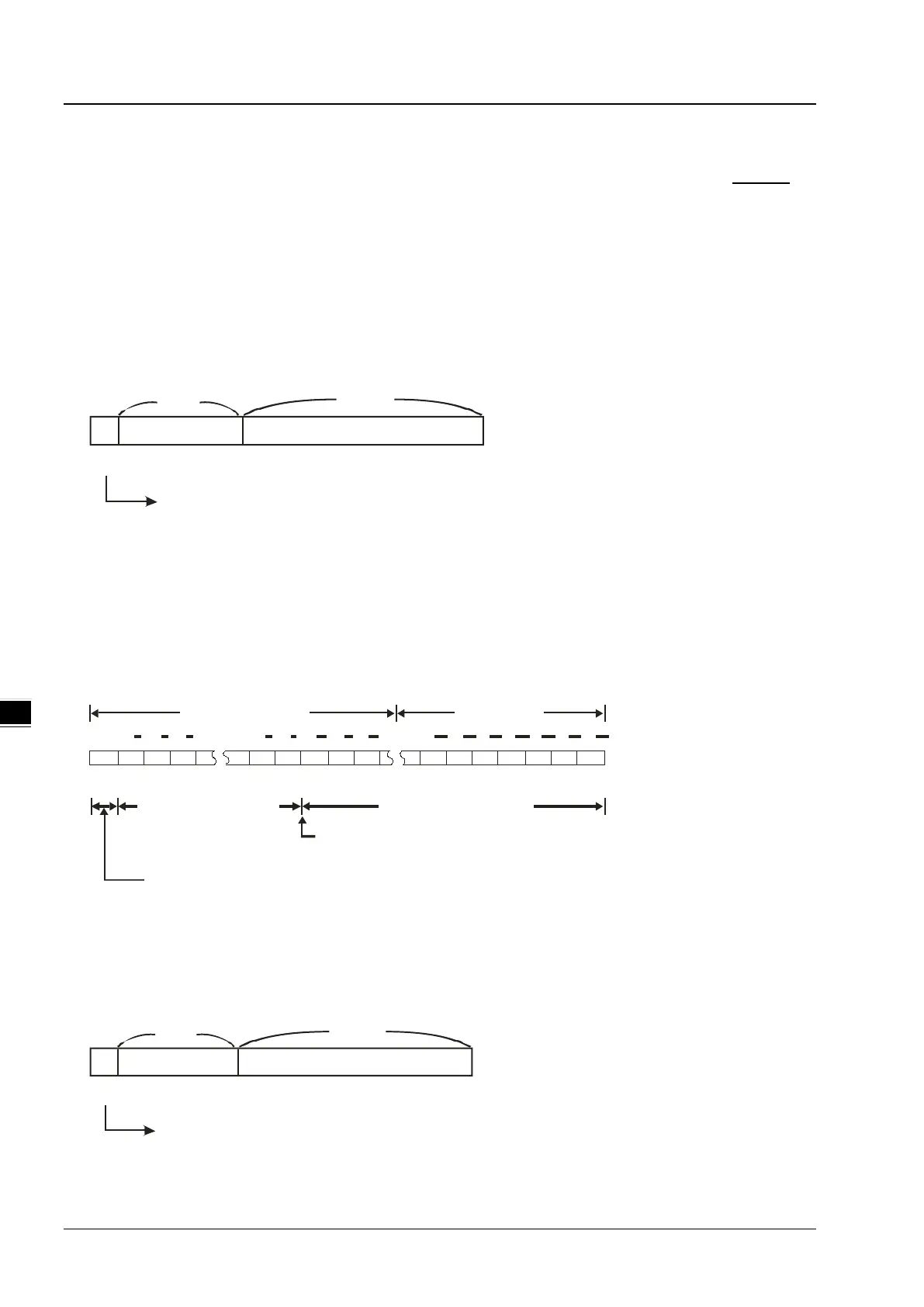
Single-precision Floating-point Numbers
The floating-point number is represented by the 32-bit register. The representation adopts the IEEE754 standard, and
the format is as follows.
S
Exponent
Mantissa
8-bit 23-bit
b
31
b
0
Sign bit
0: Positive
1: Negative
Equation:
( )
127;.121 =××
BM
BE
S
The single-precision floating-point numbers range from ±2
-126
to ±2
+128
, and correspond to the range from
±1.1755×10
-38
to ±3.4028×10
+38
.
The AH500 series PLC uses two consecutive registers to form a 32-bit floating-point number. Take (D1, D0) for
example.
S E7 E6 E5 E1 E0 A22 A21 A20 A6 A5 A4 A3 A2 A1 A0
b0b1b2b3b4b5b6b20b21b22b23b24b28b29b30b31
2 2 2 2 2 2 2 2 2 2 2 2 22 2
D1(b15~b0) D0(b15~b0)
Exponent (8 bits)
Mantissa (23bits)
Mantissa sign bit (0: Positive; 1: Negative)
When b0~b31 are zeros, the content is zero.
The position where the decimal point is hidden
Double-precision Floating-point Numbers
The floating-point number is represented by the 64-bit register. The representation adopts the IEEE754 standard, and
the format is as follows.
S
Exponent
Mantissa
11-bit
52-bit
b
63
b
0
Sign bit
0: Positive
1: Negative

Table of Contents

Other manuals for Delta AH Series

Question and Answer IconNeed help?

Do you have a question about the Delta AH Series and is the answer not in the manual?

Delta AH Series Specifications

General IconGeneral
SeriesAH Series
TypePLC
Programming LanguageFunction Block Diagram, Structured Text
Communication PortsEthernet, RS-232, RS-485
Power Supply24V DC

Summary

Preface

Introduction to AH Motion Controller Operation

Introduces the AH series Motion Controller CPU, system overview, programming, and troubleshooting.

Related AH Motion Controller Manuals

Lists other relevant manuals for AH Motion Controller series and AH500 series.

Navigation Between Manuals

Explains how to navigate and reference different manuals for system configuration and applications.

Chapter 1 Introduction to Motion Control Operation

Features of AH Motion

Details the advanced motion control capabilities, including PLCopen instructions and network communications.

AH Motion System Configurations

Describes the basic configurations of the AH Motion Controller series, including network and module setup.

Basic Operating Procedures for Motion Control

Outlines the fundamental steps for setting up and operating the AH Motion Control system.

Specifications of AH Motion CPU

Provides detailed environmental and general specifications for the AHxxEMC-5A series CPU.

Chapter 2 Hardware Setup

Installation Procedures

Covers the essential steps for installing the motion controller system, including CPU rack and backplane mounting.

Wiring Guidelines

Explains the connection structure and wiring for power supply and CPU modules.

Chapter 3 Software Setup

Installing and Uninstalling ISPSoft

Details the system requirements and step-by-step procedures for installing and uninstalling ISPSoft.

Installing and Uninstalling COMMGR

Provides instructions for installing and uninstalling the COMMGR software, a communication manager.

Connecting ISPSoft with AH Motion CPU

Describes the methods for connecting ISPSoft to the AH Motion Controller CPU via USB or Ethernet.

Chapter 4 Operating ISPSoft

Quick Start Example

Provides a simple example to guide users through creating a ladder diagram in ISPSoft.

Creating a Project in ISPSoft

Outlines the procedures for creating and managing projects within the ISPSoft software.

Creating a New Project

Details the steps for creating a new project, including naming and PLC type selection.

Hardware Configuration

Explains how to configure hardware components, including backplanes and modules within HWCONFIG.

Setting CPU and Module Parameters

Covers setting parameters for CPU modules and extension modules within ISPSoft's configuration windows.

Setting Module Parameters

Details parameter settings for various Analog Input/Output and Temperature Modules.

Setting PLC Parameters

Explains how to configure PLC parameters, specifically focusing on IO Input Filters.

Creating a Ladder Program

Guides users through the process of creating a traditional ladder diagram in ISPSoft.

Testing and Debugging a Program

Covers creating connections, downloading programs, and performing connection tests for debugging.

Setting a Real-time Clock

Explains how to set the real-time clock of the PLC using ISPSoft's tools.

Chapter 5 Understanding Common Devices

Introduction to Common Devices

Introduces common devices used in programming, including symbols and enumerations.

Common Devices Overview

Describes concepts of values, strings, and devices like relays, timers, and data registers.

EtherCAT Symbols

Details the EtherCAT symbols used to read states of EtherCAT slaves within ISPSoft.

Symbols and Data Types

Explains the application, classes, and data types of symbols used in PLC programming.

User-defined Data Type (ENUM)

Describes the user-defined data type for enumeration (ENUM) and its setting methods.

Chapter 6 Understanding Motion Control Devices

Motion Control Devices Overview

Introduces motion control devices used for configuring motion axis parameters in ISPSoft.

Structures Applicable for Motion Control

Details the PLCopen structures like AXIS_REF, AXES_GROUP_REF, and TRIGGER_REF.

Parameters for Motion Axes

Explains axis parameters grouped under the AXIS_REF structure for motion axis setup.

Chapter 7 Motion Control Programming

Introduction to Motion Control Programming

Explains programming concepts like Program Organization Units (POUs) and tasks related to IEC 61131-3.

Motion Control Program Architecture

Describes the program architecture and types of POUs (PROGs, FBs) within ISPSoft.

Motion Control Instructions

Lists and explains motion control instructions, including DFB and MC instructions.

Axis Configuration

Details parameters for configuring motion axes, including type, speed, and position settings.

State Transitions

Illustrates state transitions for single-axis and multi-axis motion control based on PLCopen standards.

Buffer Mode Operations

Explains the six buffer modes available for executing sequential motion instructions.

Execution of Function Block Instructions

Defines the common interface of motion control function blocks, including inputs, outputs, and timing diagrams.

Axis Positions

Describes position types and applicable positions for servo and virtual axes in motion control.

Electronic Cam Operation

Introduces electronic cam (e-cam) operations and steps for applying e-cam using software settings.

Chapter 8 Memory Cards

Overview of Memory Cards

Provides information on memory card types, appearances, and specifications, focusing on SD and SDHC.

Using a Memory Card

Explains the process of formatting a memory card for use with the AH Motion Controller CPU.

Installing and Removing a Memory Card

Details the procedure for installing and removing memory cards from the CPU's SD slot.

Memory Card Contents and Structure

Describes the initialization and default folder structure of a memory card used with the AH system.

Reading and Writing Memory Card Data

Covers backing up and restoring system data using memory cards and the CARD Utility.

CARD Utility Functions

Explains the functionalities of the CARD Utility for backup, restore, and project export operations.

System Backup Procedures

Details the step-by-step process for backing up system data to a memory card or PC.

System Restoration Procedures

Guides users through restoring system data from backup files to the CPU or ISPSoft project.

Chapter 9 Troubleshooting

Inspection and Troubleshooting

Provides basic inspection steps and procedures for identifying and resolving system errors.

Error Codes and Indicators

Lists and explains error codes, descriptions, CPU status, and LED indicator behaviors.

Troubleshooting CPU Errors

Offers corrective actions for various CPU errors indicated by ERROR and BUS FAULT LEDs.

Troubleshooting I/O Modules

Provides guidance for troubleshooting errors related to Analog I/O and Temperature Measurement Modules.

Troubleshooting Limitation Errors

Addresses software and hardware limit errors, including error codes and handling processes.

Appendices

Installing USB Driver for AH Motion CPU

Step-by-step guide for installing the USB driver for AH Motion CPU on Windows 7.

Device Addresses Overview

Lists standard Modbus and AHxxEMC device addresses for various device types.

CPU Module Operating Principles

Explains the operation, diagnosis, I/O refreshing, and communication service of the CPU module.

Related product manuals