6. Function blocks
6.1 Manufacturer function blocks
Note on the minimum time setting:
If a time value is less than the program cycle time, the elapsed
time will not be recognized until the next cycle. This may cause
unforeseeable switching states.
Analog value and timing relay setpoint
If you wish to use variable values as a timing relay setpoint, such as an analog input,
the following conversion rules apply, depending on the time base configured.
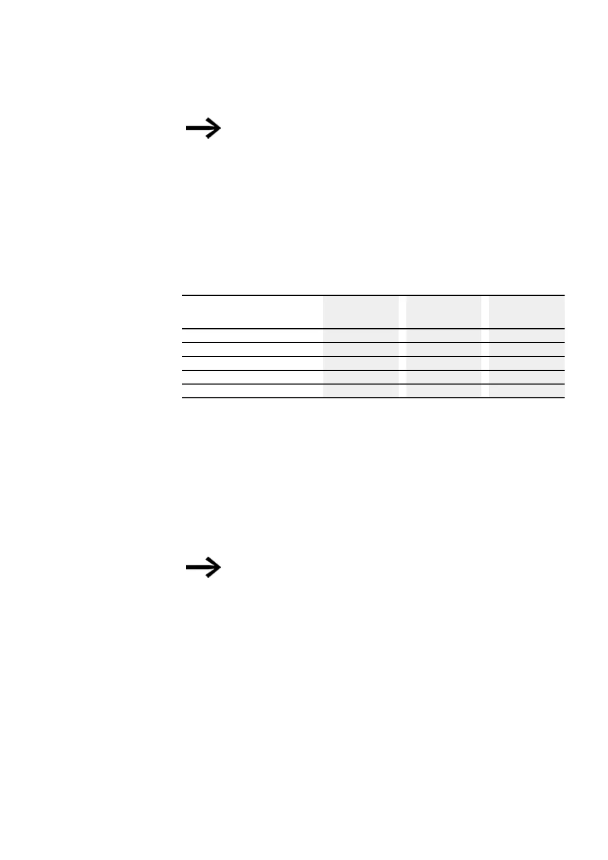
S time base
Equation: Time setpoint = ( Variable value/10) in [ms]
Variable Value Time setpoint
in [s]
Time setpoint
in [mm:ss]
Time setpoint
in [hh:mm]
0 (Minimum) 00:000 00:00 00:00
100 00:108 01:04 01:04
300 00:308 05:00 05:00
500 00.507 08:02 10:06
4095 (Maximum) 04:099 68:15 68:15
M:S time base
Rule: Time setpoint = Variable value/60
Integer
=
Number of minutes,
Residual
=
Number of seconds
Time base H:M
Rule: Time setpoint = Variable value/60
Integer
=
Number of hours,
Residual
=
Number of minutes,
You can only use analog values as setpoints if the value of the
analog input is stable. Fluctuating analog values impair a repro-
ducible timing response.
Signal Diagrams
The fact that the function block features various operating modes means that it can
work in more than one way as shown below.
How the timing relay works with the on-delayed operating mode with and without
random times
Random switching
The contact of the timing relays switches randomly within the SETPOINT value range.
easyE4 11/18 MN050009 EN www.eaton.com
199