6. Function blocks
6.1 Manufacturer function blocks
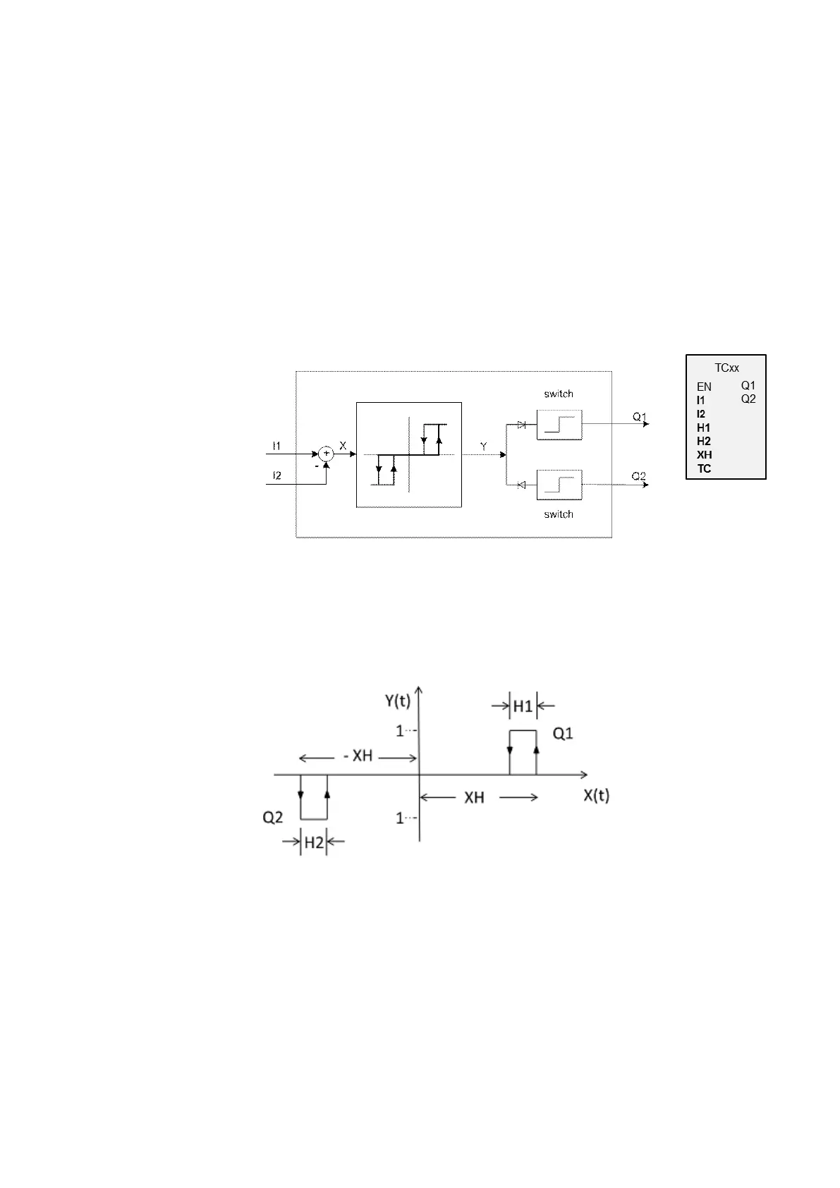
6.1.4.4 TC - Three step controller
General
TC three-step controllers feature three states for the manipulated
variable. These states are implemented with two function block out-
puts Q1, Q2, of which either none or only one can be closed. I1 is the
setpoint and I2 is the actual value. X = I1 - I2 yields control deviation
X, which is applied on the actual controller. The controller will then
determine the manipulated variable for function block outputs Q1, Q2.
Figure 157: Three-step controller schematic diagram
I1: Setpoint
I2: Actual value
Operating principle
The following timing diagram shows how the three-step controller behaves.
Figure 158: Timing diagram for three-step controller
XH/ -XH: Distance X from switching point
H1: Hysteresis 1 for XH
H2: Hysteresis 2 for -XH
Y(t): Operating points for Q1/ Q2
Q1: Switch output X = positive
Q2: Switch output X = negative
easyE4 11/18 MN050009 EN www.eaton.com
297