6. Function blocks
6.1 Manufacturer function blocks
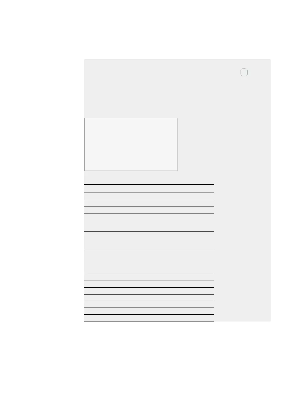
SR01 configuration on device display
When using the function block in the circuit diagram for the first time, use OK to auto-
matically enter the display of function blocks on the device display, as shown in the fol-
lowing figure. After defining shift register number 01, you set here the following
parameters:
l The DW operating mode for the double word marker format.
l The double word markers for receiving the production code.
SR01 DW +
>I1 MD11
>I2
D1> MD01
D2> MD02
D3> MD03
D4>
D5>
D6>
D7>
D8>
Figure 174: Parameters on the device display
Enter the function block settings here. The display contains the following elements:
SR01 shift register Function block: SR shift register, number 01
DW Operating mode: Double word
+ Parameter set can be called via the PARAMETERS menu
>I1 Input value DW forwards:
Integer value range:
-2,147,483,648 to +2,147,483,647
>I2 Input value DW backwards:
Integer value range:
-2,147,483,648 to +2,147,483,647
D1> Register value 1 of the shift register,
Integer value range:
-2,147,483,648 to +2,147,483,647
for all registers
D2> Register value 2
D3> Register value 3
D4> Register value 4
D5> Register value 5
D6> Register value 6
D7> Register value 7
D8> Register value 8
332
easyE4 11/18 MN050009 EN www.eaton.com
 Loading...