27
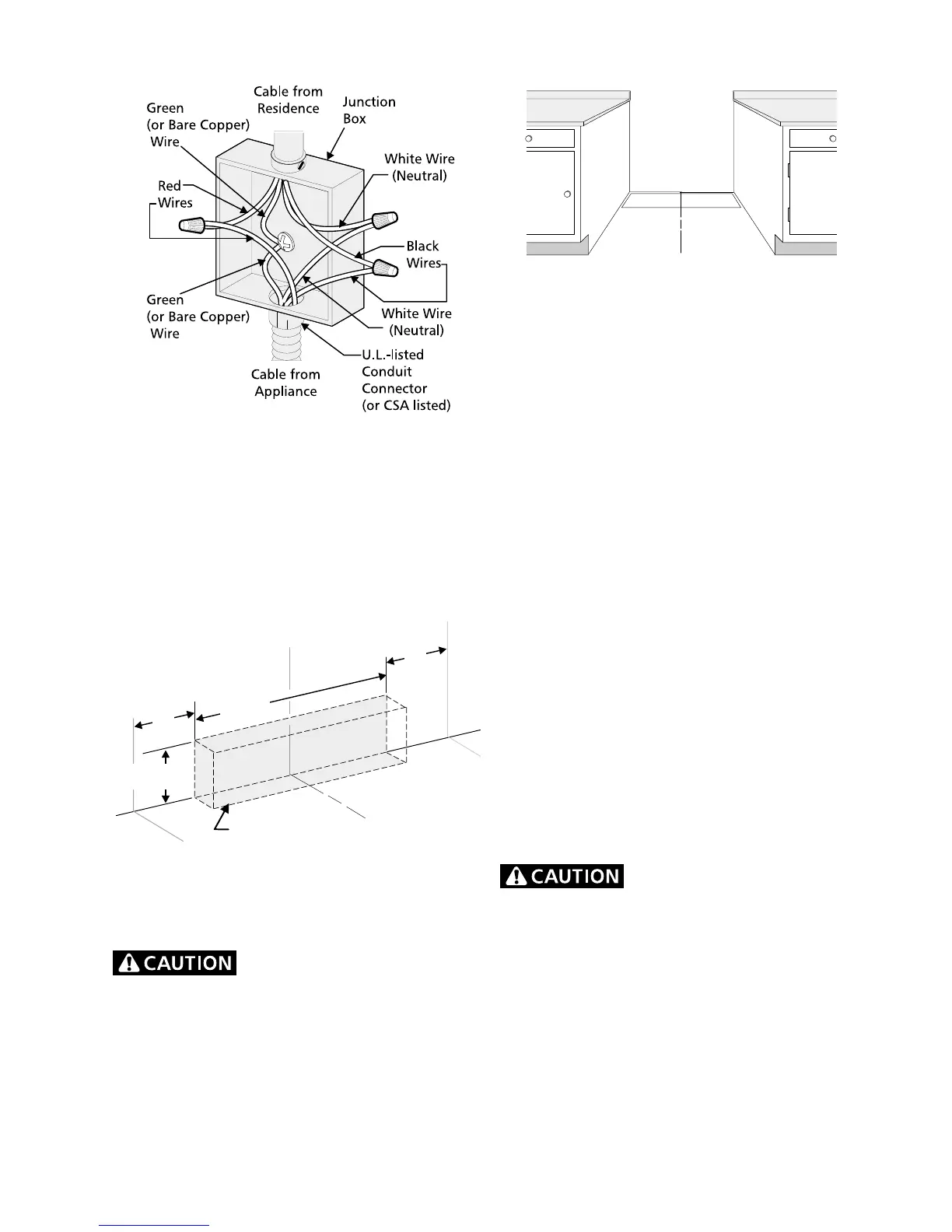
Figure 6
4-Wire Electrical System
(example: Junction Box)
Junction Box Location
Locate junction box as shown in Figure 7.
If a service cord is used, the wall receptacle should
be located in accordance with the dimensions
below.
Figure 7
Range Placement
To eliminate the risk of burns or
fire by reaching over heated surface units, cabinet
storage space located above the range should be
avoided. If cabinet storage space is to be provided,
the risk can be reduced by installing a range hood
that projects horizontally a minimum of 5" (12.7 cm)
beyond the bottom of the cabinet.
Figure 8
If range will be installed with a cabinet on both
sides, draw a center line on the floor between the
cabinets (see figure 8). If back of range will not
be flush with the wall (the location of the outlet
may not allow the range to be positioned against the
wall), draw a line on the floor where the back edge of
the range will be. Now install anti-tip brackets.
If range will be installed with a cabinet on one
side only, move the range into final position. Draw a
line on the floor along the side of the range that is
not against the cabinet. If back of range will not
be flush with the wall (the location of the outlet
may not allow the range to be positioned against the
wall), draw a line on the floor where the back edge of
the range will be. Now install anti-tip brackets (see
"Anti-Tip Brackets Installation").
If range will not be installed against a cabinet,
move range into final position. Mark on the floor
along both sides of the range. If back of range will
not be flush with the wall (the location of the
outlet may not allow the range to be positioned
against the wall), draw a line on the floor where the
back edge of the range will be. Now install anti-tip
brackets.
Range Installation
When unpacking the range, do
not discard the 4 shipping bolts. These are to be
replaced on the unit for use as leveling legs and
height adjustments.
1. The back of the range may be installed directly
against the rear wall of the structure.
2. These ranges conform to U.L. requirements for
"0" spacing from the range to adjacent vertical
walls above the countertop level. However, to
reduce possible scorching of vertical walls and
to minimize potential fire hazards under
abnormal surface unit use conditions such as
Follow instructions for
the type of installation you have
Center
Line of
Range
Locate Electrical Hook-up
Inside Shaded Area
Center
Line of
Range
10"
(25.4 cm)
10"
(25.4 cm)
7" Max.
(17.8 cm Max.)
20"
(50.8 cm)
FLOOR
WALL
Center
Line of
Range
 Loading...