&
Start signal
Trip Signal&
Timer Blocking signals
1
V00654
Timer Settings
Threshold
IDMT/ DT
Timer Blocking settings
Stage Blocking signals
1
Stage Blocking settings
Function inhibit
Directional Check
&
Energising quantity
Voltage
Current
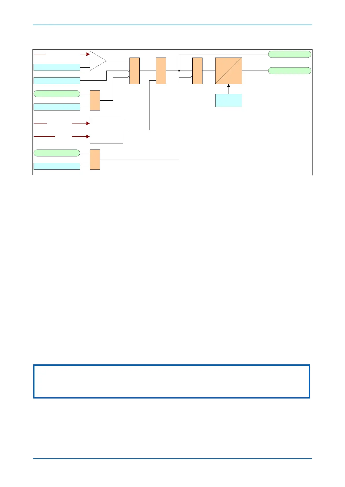
Figure 33: Principle of protection function implementation
An ener
gising quantity is either a v
oltage input from a system voltage transformer, a current input from a system
current transformer or another quantity derived from one or both of these. The energising quantities are extracted
from the power system. The signals are converted to digital quantities where they can be processed by the IEDs
internal processor.
In general, an energising quantity, be it a current, voltage, power, frequency, or phase quantity, is compared with a
threshold value, which may be settable, or hard-coded depending on the function. If the quantity exceeds (for
overvalues) or falls short of (for undervalues) the threshold, a signal is produced, which when gated with the
various inhibit and blocking functions becomes the Start signal for that protection function. This Start signal is
generally made available to Fixed Scheme Logic (FSL) and Programmable Scheme Logic (PSL) for further
processing. It is also passed through a timer function to produce the Trip signal. The timer function may be an
IDMT curve, or a Definite Time delay, depending on the function. This timer may also be blocked with timer
blocking signals and settings. The timer can be configured by a range of settings to define such parameters as the
type of curve, The Time Multiplier Setting, the IDMT constants, the Definite Time delay etc.
In General Electric products, there are usually several independent stages for each of the functions, and for three-
phase functions, there are usually independent stages for each of the three phases.
Typically some stages use an Inverse Definite Minumum time (IDMT) timer function, and others use a Definite Time
timer (DT) function. If the DT time delay is set to '0', then the function is known to be "instantaneous". In many
instances, the term 'instantaneous protection" is used loosely to describe Definite Time protection stages, even
when the stage may not theoretically be instantaneous.
Many protection functions require a direction-dependent decision. Such functions can only be implemented where
both current and voltage inputs are available. For such functions, a directional check is required, whose output can
block the Start signal should the direction of the fault be wrong.
Note:
In the logic diagrams and descriptive text, it is usually sufficient to show only the first stage, as the design principles for
subsequent stages are usually the same (or at least very similar). Where there are differences between the functionality of
different stages, this is clearly indicated.
2.2.1 TIMER HOLD FACILITY
The Timer Hold facility is available for stages with IDMT functionality , and is controlled by the timer reset settings
for the r
elevant stages (e.g. I>1 tReset, I>2 tReset ). These cells are not visible for the IEEE/US curves if an inverse
Chapter 6 - Current Protection Functions P14x
96 P14xEd1-TM-EN-1
 Loading...


