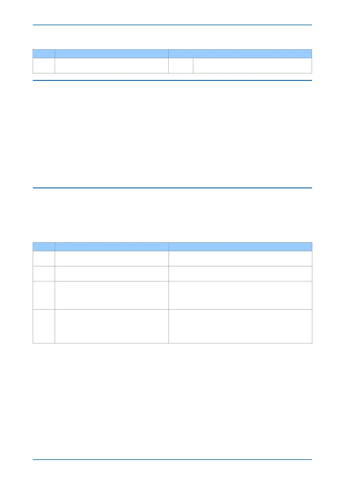
Test Check Action
8
The VT type field in the model number is incorrect (no VTs
fitted)
3.5 ERROR CODE DURING OPERATION
The IED performs continuous self-checking. If the IED detects an error it displays an error message, logs a
maintenance recor
d and after a short delay resets itself. A permanent problem (for example due to a hardware
fault) is usually detected in the power-up sequence. In this case the IED displays an error code and halts. If the
problem was transient, the IED reboots correctly and continues operation. By examining the maintenance record
logged, the nature of the detected fault can be determined.
3.5.1 BACKUP BATTERY
If the IED’s self-check detects a failure of the lithium battery, the IED displays an alarm message and logs a
maintenance r
ecor
d but the IED does not reset.
To prevent the IED from issuing an alarm when there is a battery failure, select DATE AND TIME then Battery Alarm
then Disabled. The IED can then be used without a battery and no battery alarm message appears.
3.6 MAL-OPERATION DURING TESTING
3.6.1 FAILURE OF OUTPUT CONTACTS
An apparent failure of the relay output contacts can be caused by the configuration. Perform the following tests to
identif
y the r
eal cause of the failure. The self-tests verify that the coils of the output relay contacts have been
energized. An error is displayed if there is a fault in the output relay board.
Test Check Action
1 Is the Out of Service LED ON?
If this LED is ON, the relay may be in test mode or the protection has
been disabled due to a hardw
are verify error.
2
Examine the Contact status in the Commissioning
section of the menu.
If the relevant bits of the contact status are operated, go to test 4; if not,
go to test 3.
3
Examine the fault record or use the test port to check the
pr
otection element is operating corr
ectly.
If the protection element does not operate, check the test is correctly
applied.
If the protection element operates, check the programmable logic to
make sure the protection element is correctly mapped to the contacts.
4
Using the Commissioning or Test mode function, apply a
test pattern to the relev
ant relay output contacts.
Consult the correct external connection diagram and use
a continuity tester at the rear of the relay to check the
relay output contacts operate.
If the output relay operates, the problem must be in the external wiring
to the relay. If the output relay does not operate the output relay
contacts may have failed (the self-tests verify that the relay coil is being
energized). Ensure the closed resistance is not too high for the continuity
tester to detect.
3.6.2 FAILURE OF OPTO-INPUTS
The opto-isolated inputs are mapped onto the IED's internal DDB signals using the programmable scheme logic. If
an input is not recognised by the scheme logic, use the Opt
o I/P Status cell in the COMMISSION TESTS column to
check whether the problem is in the opto-input itself, or the mapping of its signal to the scheme logic functions.
If the device does not correctly read the opto-input state, test the applied signal. Verify the connections to the
opto-input using the wiring diagram and the nominal voltage settings in the OPTO CONFIG column. To do this:
1. Select the nominal voltage for all opto-inputs by selecting one of the five standard ratings in the Global
Nominal V cell.
2. Select Custom to set each opto-input individually to a nominal voltage.
3. Using a voltmeter, check that the voltage on its input terminals is greater than the minimum pick-up level
(See the Technical Specifications chapter for opto pick-up levels).
Chapter 22 - Maintenance and Troubleshooting P14x
526 P14xEd1-TM-EN-1
 Loading...


