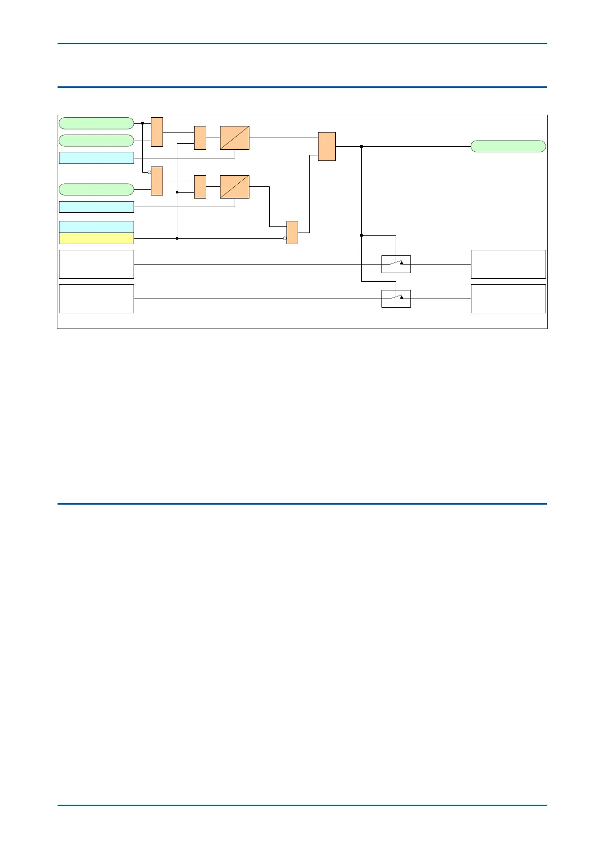
6.2 CLP LOGIC
CLP Initiate
CB Open 3 ph
1
CB Closed 3 ph
1
Cold Load Pickup
Enabled
&
&
tcold
tclp
S
R
Q
CLP Operation
V00635
Applied Current
Threshold
Applied Timer Settings
Current threshold setting
in CLP column
Timer settings in CLP
column
1
tclp Time Delay
tcold Time Delay
Figure 42: Cold Load Pickup logic
The CLP Operation signal indicates that CLP logic is in operation. This only happens when CLP is enabled AND CLP
is initiated either externally or from a CB Open condition after the t
cold period has elapsed. The CLP Operation
indicator goes low when CLP is disabled or when the external CLP trigger is removed or when there is a CB closed
condition.
tcold and tclp are initiated via the CB open and CB closed signals generated within the device. These signals are
produced by connecting auxiliary contacts from the circuit breaker or starting device to the IED's opto-inputs
If dual CB contacts are not available (one for Open (52a) and for Close (52b)) you can configure the device to be
driven from a single contact (either 52a or 52b). The device would then simply invert one signal to provide the
other. This option is available using the CB status input cell in the CB CONTROL column. The setting can be set to
None, 52a, 52b or 52a and 52b.
6.3 APPLICATION NOTES
6.3.1 CLP FOR RESISTIVE LOADS
A typical example of where CLP logic may be used is for resistive heating loads such as such as air conditioning
systems. R
esistiv
e loads typically offer less resistance when cold than when warm, hence the start-up current will
be higher.
To set up the CLP, you need to select Enable from the I> status option to enable the settings of the temporary
current and time settings. These settings should be chosen in accordance with the expected load profile. Where it
is not necessary to alter the setting of a particular stage, the CLP settings should be set to the same level as the
standard overcurrent settings.
It may not be necessary to alter the protection settings following a short supply interruption. In this case a suitable
tcold timer setting can be used.
6.3.2 CLP FOR MOTOR FEEDERS
In general, a dedicated motor protection device would protect feeders supplying motor loads. However, if CLP logic
is av
ailable in a feeder device, this may be used to modif
y the overcurrent settings during start-up.
Depending on the magnitude and duration of the motor starting current, it may be sufficient to simply block
operation of instantaneous elements. If the start duration is long, the time-delayed protection settings may also
P14x Chapter 6 - Current Protection Functions
P14xEd1-TM-EN-1 111
 Loading...


