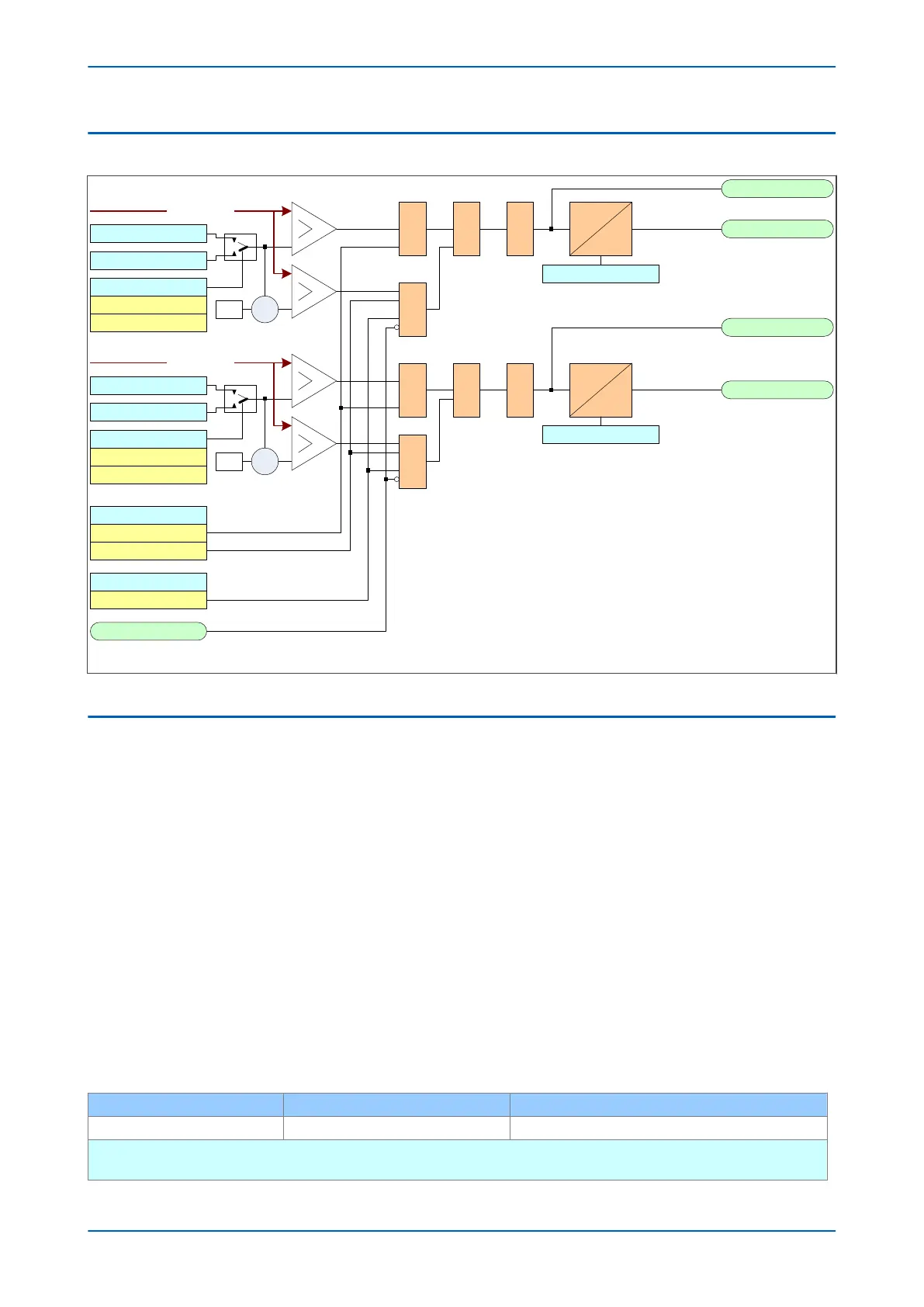
2.2 OVERPOWER LOGIC
Power>1 Trip
Power>1 Mode
V00900
DT
Power>1 Start
Power>1 3Ph Trip
Power>1 3PhStart
VTS Slow Block
Power>1 1Ph Watt
Power>1 1Ph VAR
&
&
Power>1 Status
Enabled
&
&
Power>1Direction
Forward
& 1
Reverse
X
-1
1
&
Active
Reactive
Power>1 Mode
Power>1 3Ph Watt
Power>1 3Ph VAR
X-1
Active
Reactive
Power>1TimeDelay
DT
Power>1TimeDelay
P(A, B, or C)
P(3 phase )
Figure 137: Overpower logic
2.3 APPLICATION NOTES
2.3.1 FORWARD OVERPOWER SETTING GUIDELINES
The relevant power threshold settings should be set greater than the full load rated power.
The operating mode should be set to Forw
ard.
A time delay setting (Power>(n) TimeDelay) should be applied. This setting is dependant on the application, but
would typically be around 5 seconds. The delay on the reset timer (Power>(n) tRESET), would normally be set to
zero.
2.3.2 REVERSE POWER CONSIDERATIONS
A generator is expected to supply power to the connected system in normal operation. If the generator prime
mov
er fails, it will begin to motor (if the pow
er system to which it is connected has other generating sources). The
consequences of generator motoring and the level of power drawn from the power system will be dependent on
the type of prime mover.
Typical levels of motoring power and possible motoring damage that could occur for various types of generating
plant are given in the following table.
Prime mover Motoring power Possible damage (percentage rating)
Diesel Engine 5% - 25% Risk of fire or explosion from unburned fuel
Motoring level depends on compression ratio and cylinder bore stiffness. Rapid disconnection is required to limit power loss
and risk of damage.
P14x Chapter 12 - Power Protection Functions
P14xEd1-TM-EN-1 261
 Loading...


