18 BUSBAR PROTECTION
Busbars are the nerve centers of the power system. This is where power lines are connected together in a
substation. Essentially a bus bar is a robust and highly conductiv
e metal framework, onto which power lines are
connected.
Busbars can pass current from a large number of lines, so a fault on the busbar could result in an extremely large
fault current resulting in enormous damage. Faults on busbars are generally rare, but because of the extreme
consequence in the event of failure, it is generally wise to provide dedicated protection for them.
Because the connections to busbars are close together, differential protection offers a convenient solution for
busbar protection. Using the principle of Kirchoff’s law, we need only to compare the sum of the incoming currents
with the sum of the outgoing current and establish the difference. If there is a significant difference, then this
indicates a fault on the busbar.
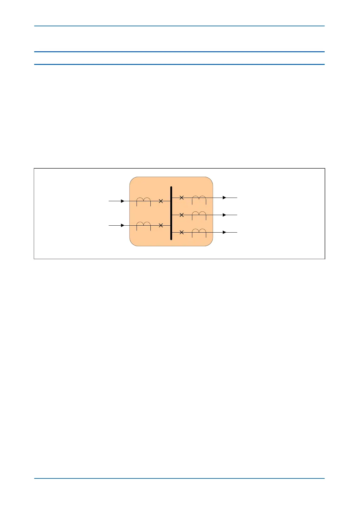
The following figure shows a simplified busbar with two input lines and three output lines.
Protection zone
I
in1
I
out1
I
out2
I
out3
I
in2
V00750
Figure 84: Simplified busbar representation
In this example, if the vector sum of Iin1, Iin2, Iout1, Iout2 and Iout3 = 0, ther
e is no fault. If the vector sum is not
equal to zero, then there is a fault.
There are various protection techniques for busbars, but the technique which is most commonly used is high
impedance differential protection. A standard overcurrent protection element can be used for this purpose.
For high impedance differential protection, we need to connect the secondary windings of identical current
transformers in parallel, then measure the summed current as follows:
P14x Chapter 6 - Current Protection Functions
P14xEd1-TM-EN-1 159
 Loading...


