Note:
Residual v
oltage is nominally 180° out of phase with residual current. Consequently, the DEF elements are polarised from the
"-Vres" quantity. This 180° phase shift is automatically introduced within the device.
The directional criteria with residual voltage polarisation is given below:
● Dir
ectional for
ward: -90° < (angle(IN) - angle(VN + 180°) - RCA) < 90°
● Directional reverse : -90° > (angle(IN) - angle(VN + 180°) - RCA) > 90°
Most of the models derive the Residual Voltage quantity internally, from the 3-phase voltage input supplied from
either a 5-limb VT or three single-phase VTs.
The P144, however, measures this voltage from the residual voltage input which must be supplied from a suitable
broken delta VT. This type of VT allows the passage of residual flux and consequently allows the device to derive
the required residual voltage. The primary star point of the VT must be earthed. A three-limb VT has no path for
residual flux and is therefore unsuitable to supply the device.
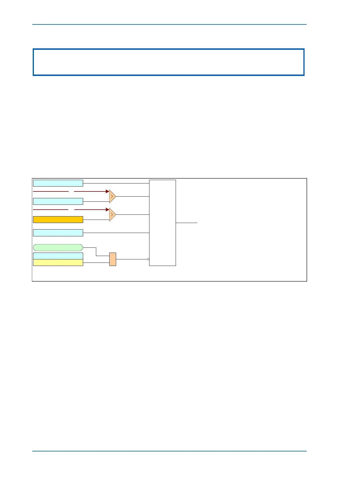
10.4.1.1 DIRECTIONAL EARTH FAULT LOGIC WITH RESIDUAL VOLTAGE POLARISATION
V00612
VTS Slow Block
IN1> Blocking
VTS Blocks IN>1
VN
IN1> VNpol Set
Directional
check
IN1 > DIRECTIONAL
IN1
Low Current Threshold
&
To EF logic
IN1> Char Angle
Note: This diagram shows the logic for IN1 (measured earth fault ). The logic for
IN2 (derived earth fault ) follows similar principles.
This diagram does not show all stages . Other stages follow similar principles.
Figure 50: Directional EF logic with neutral voltage polarization (single stage)
Voltage Transformer S
upervision (VTS) selectively blocks the directional protection or causes it to revert to non-
directional operation. When selected to block the directional protection, VTS blocking is applied to the directional
checking which effectively blocks the Start outputs as well.
10.4.2 NEGATIVE SEQUENCE POLARISATION
In some applications, the use of residual voltage polarisation may be not possible to achieve, or at the very least,
pr
oblematic. For example, a suitable type of V
T may be unavailable, or an HV/EHV parallel line application may
present problems with zero sequence mutual coupling.
In such situations, the problem may be solved by using Negative Phase Sequence (NPS) quantities for polarisation.
This method determines the fault direction by comparing the NPS voltage with the NPS current. The operating
quantity, however, is still residual current.
This can be used for both the derived and measured standard earth fault elements. It requires a suitable voltage
and current threshold to be set in cells IN> V2pol set and IN> I2pol set respectively.
Negative phase sequence polarising is not recommended for impedance earthed systems regardless of the type
of VT feeding the relay. This is due to the reduced earth fault current limiting the voltage drop across the negative
sequence source impedance to negligible levels. If this voltage is less than 0.5 volts the device will stop providing
directionalisation.
P14x Chapter 6 - Current Protection Functions
P14xEd1-TM-EN-1 123
 Loading...


