3 SCHEME LOGIC
The product is supplied with pre-loaded Fixed Scheme Logic (FSL) and Programmable Scheme Logic (PSL).
The Scheme Logic is a functional module within the IED
, through which all mapping of inputs to outputs is handled.
The scheme logic can be split into two parts; the Fixed Scheme Logic (FSL) and the Programmable Scheme Logic
(PSL). It is built around a concept called the digital data bus (DDB). The DDB encompasses all of the digital signals
(DDBs) which are used in the FSL and PSL. The DDBs included digital inputs, outputs, and internal signals.
The FSL is logic that has been hard-coded in the product. It is fundamental to correct interaction between various
protection and/or control elements. It is fixed and cannot be changed.
The PSL gives you a facility to develop custom schemes to suit your application if the factory-programmed default
PSL schemes do not meet your needs. Default PSL schemes are programmed before the product leaves the
factory. These default PSL schemes have been designed to suit typical applications and if these schemes suit your
requirements, you do not need to take any action. However, if you want to change the input-output mappings, or
to implement custom scheme logic, you can change these, or create new PSL schemes using the PSL editor.
The PSL consists of components such as logic gates and timers, which combine and condition DDB signals.
The logic gates can be programmed to perform a range of different logic functions. The number of inputs to a logic
gate are not limited. The timers can be used either to create a programmable delay or to condition the logic
outputs. Output contacts and programmable LEDs have dedicated conditioners.
The PSL logic is event driven. Only the part of the PSL logic that is affected by the particular input change that has
occurred is processed. This minimises the amount of processing time used by the PSL ensuring industry leading
performance.
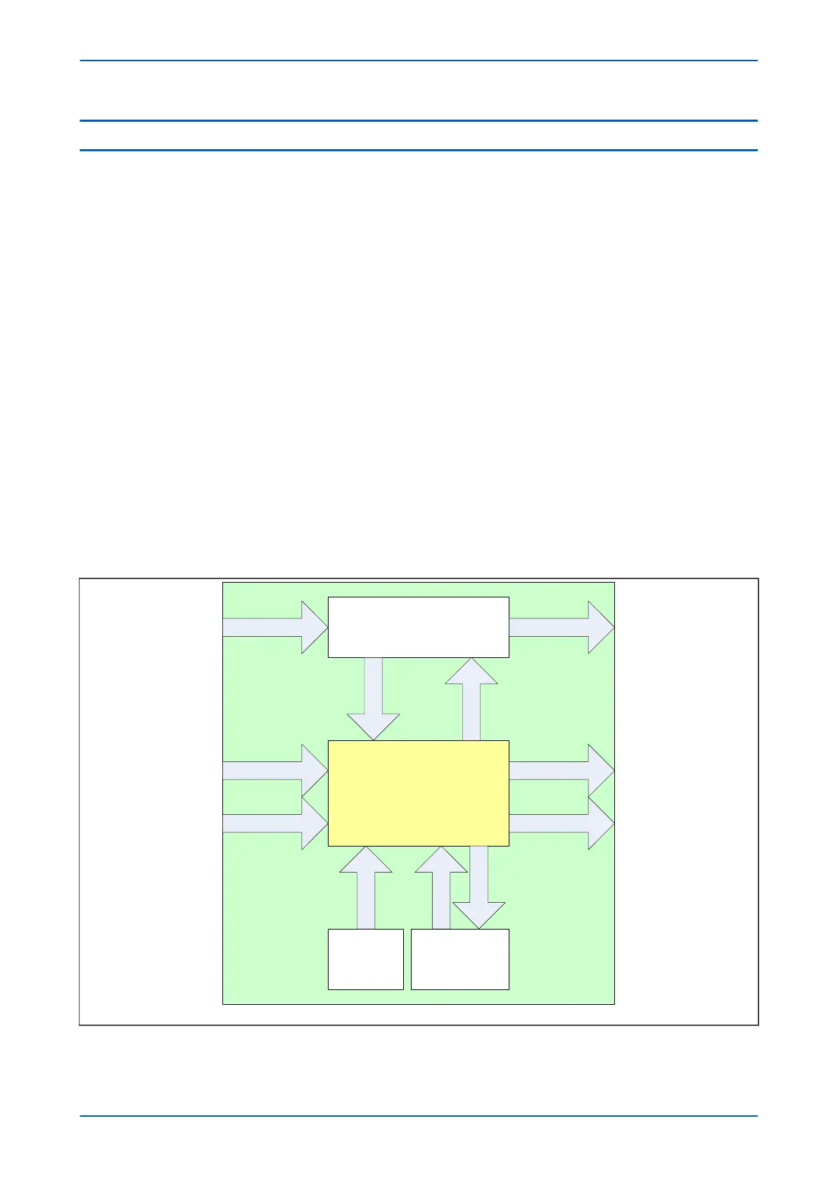
The following diagram shows how the scheme logic interacts with the rest of the IED.
V02011
PSL and FSL
Protection functions
S
L
i
n
p
u
t
s
S
L
o
u
t
p
u
t
s
Opto-inputs Programmable LEDs
Output relaysFunction keys
G
o
o
s
e
i
n
p
u
t
s
Control input
mo
dule
G
o
o
s
e
o
u
t
p
u
t
s
Ethernet
pr
ocessing module
Fixed LEDs
C
o
n
t
r
o
l
i
n
p
u
t
s
Energising quantities
Figure 183: Scheme Logic Interfaces
P14x Chapter 16 - Digital I/O and PSL Configuration
P14xEd1-TM-EN-1 359
 Loading...


