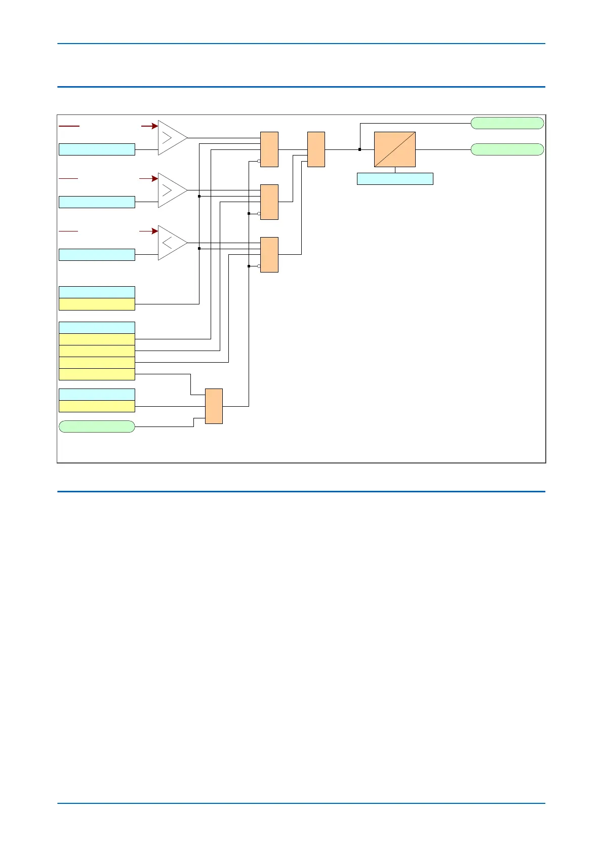
4.3 SENSITIVE POWER LOGIC
SensP 1 Trip A
V00902
SensP 1 Start A
P1 Poledead Inh
Enabled
VTS Slow Block
&
&
Aph Sens Power
Enabled
Sens P 1 Function
Over
& 1
Reverse
1
Low Forward
Disabled
Sens P >1 Setting
Sens P <1 Setting
Sens -P>1Setting
Sens P 1 Delay
DT
Note: This diagram does not show all stages . Other stages follow similar principles.
It also does not show all phases . Other phases follow similar principles.
Aph Sen Watts
Aph Sen Watts
Aph Sen Watts
Figure 139: Sensitive Power logic diagram
4.4 APPLICATION NOTES
4.4.1 SENSITIVE POWER CALCULATION
Input Quantities
Sensitive pow
er is calculated from the A-phase-neutral voltage and the A-phase sensitive current input.
The calculation for active power with the correction angle is:
P I V
A AS A C
= −cos( )
ϕ θ
where:
● P
A
= sensitive pow
er
● V
A
= A-phase voltage
● I
AS
= A-phase sensitive current
● Φ= the angle of I
AS
with respect to V
A
● θ
C
= the CT correction angle
Calculations within the device are based upon quadrature components obtained from the Fourier analysis of the
input signals. The quadrature values for V
A
and I
AS
are used for the sensitive power calculation as shown:
P14x Chapter 12 - Power Protection Functions
P14xEd1-TM-EN-1 267
 Loading...


