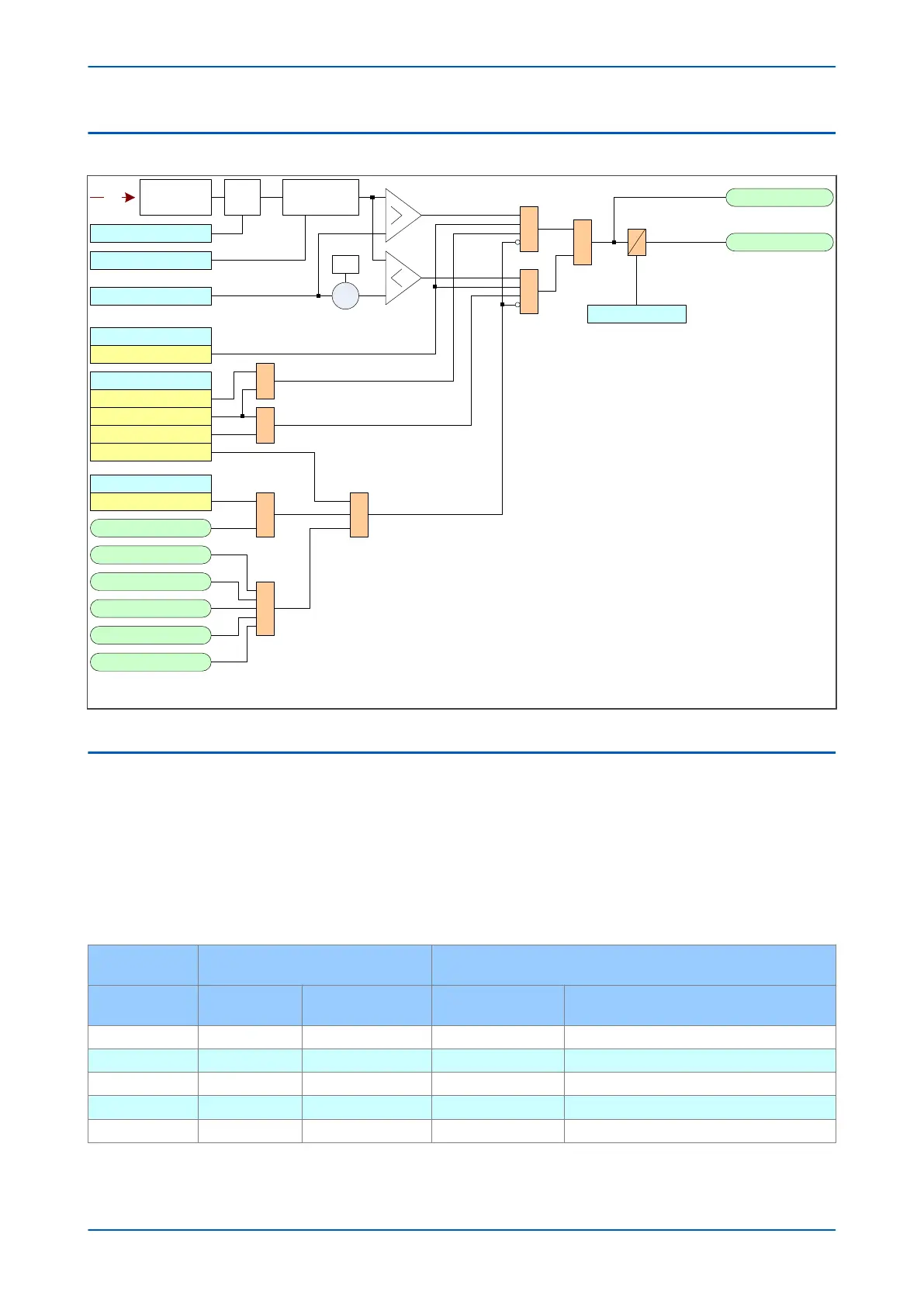
5.2 INDEPENDENT R.O.C.O.F PROTECTION LOGIC
df/dt+t 1 Status
Stg1 df/dt+t Trp
Stage 1
V00870
V Stg1 df /dt+t Sta
&
Enabled
Adv Freq Inh
Freq Not Found
V<B Status
Enabled
UV Block
1
df/dt
df/dt+t 1 Set X
-1
&
Both
Positive
Negative
Stg1 Block
1
1
1
df/dt Avg.Cycles
1
df/dt+t 1 Time
Frequency
determination
Disabled
Freq High
Freq Low
1
Smoothing
filter*
df/dt smooth fct
*Note: The smoothing filter setting only applies when the magnitude of the tracking voltage or current is changed . If
there is no change , the factor is set to 1.
Figure 129: Independent rate of change of frequency logic (single stage)
5.3 APPLICATION NOTES
5.3.1 SETTING GUIDELINES
Considerable care should be taken when setting this element because it is not supervised by a frequency setting.
Setting of the time delay or increasing the number of df/dt av
eraging cycles will improve stability but this is traded
against reduced tripping times.
It is likely that this element would be used in conjunction with other frequency based protection elements to
provide a scheme that accounts for severe frequency fluctuations. An example scheme is shown below:
Frequency "f+t [81U/81O]" Elements
Frequency Supervised Rate of Change of Frequency "f+df/dt
[81RF]" Elements
Stage
Frequency
Setting (Hz)
Time Setting (Sec.)
Frequency Setting
(Hz)
Rate of Change of Frequency Setting (Hz/
Sec.)
1 49 20 49.2 1.0
2 48.6 20 48.8 1.0
3 48.2 10 48.4 1.0
4 47.8 10 48.0 1.0
5 - - - -
P14x Chapter 11 - Frequency Protection Functions
P14xEd1-TM-EN-1 243
 Loading...


