a
b
c
C
A
B
High Z
RE
F
R
L
R
CT
R
L
R
L
R
L
R
CT
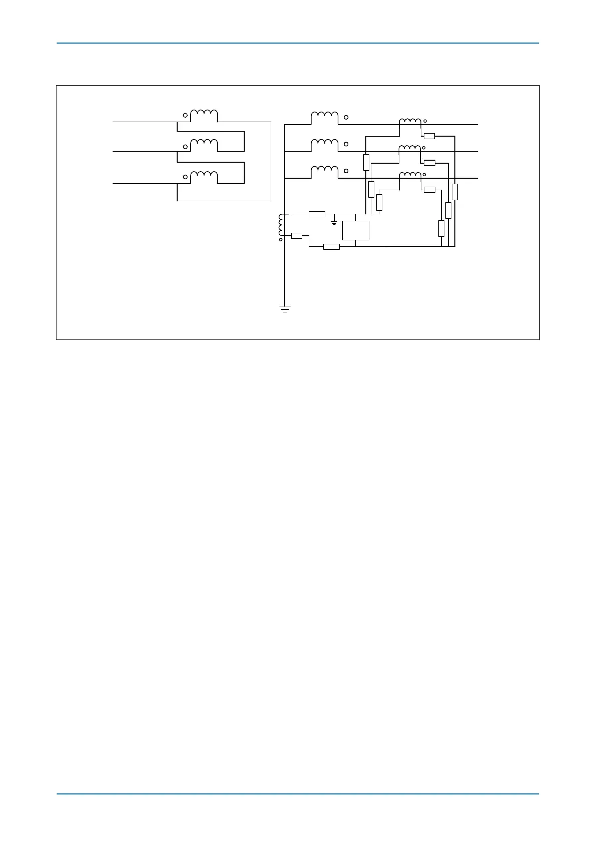
Transformer:
90 MVA
33/132 kV
Dyn11, X = 5%
Buderns:
R
CT
= 0.5 W
R
L
= 0.98 W
400:1
V00687
Figure 101: High Impedance REF for the LV winding
4.3.2.1 STABILITY VOLTAGE CALCULATION
The transformer full load current, IFLC, is:
I
FL
C
= (90 x 10
6
) / (132 x 103 x
Ö
3) = 394 A
To calculate the stability voltage the maximum through fault level should be considered. The maximum through
fault level, ignoring the source impedance, I
F
, is:
I
F
= I
FLC
/ X
TX
= 394 / 0.05 = 7873 A
The required stability voltage, VS, and assuming one CT saturated is:
V
s
= KI
F
(R
CT
+ 2R
L
)
The following figure can be used to determine the K factor and the operating time. The K factor is valid when:
● 5 ≤ X/R ≤ 120
and
● 0.5In ≤ I f ≤ 40In
We recommend a value of VK/VS = 4.
With the transformer at full load current and percentage impedance voltage of 394A and 5% respectively, the
prospective fault current is 7873 A and the required stability voltage Vs (assuming that one CT is saturated) is:
V
s
= 0.9 x 7873 x (0.5 + 2 x 0.98) / 400 = 45.5 V
The CTs knee point voltage should be at least 4 times Vs so that an average operating time of 40 ms is achieved.
4.3.2.2 PRIMARY CURRENT CALCULATION
The primary operating current should be between 10 and 60 % of the winding rated current. Assuming that the
relay effectiv
e setting or primary operating current is approximately 30% of the full load current, the calculation
below shows that a setting of less than 0.3 A is required.
Eective setting = 0.3I
FLC
/ C
T Ratio = 30.3 x 394 / 400 = approximately 0.3 A
P14x Chapter 7 - Restricted Earth Fault Protection
P14xEd1-TM-EN-1 179
 Loading...


