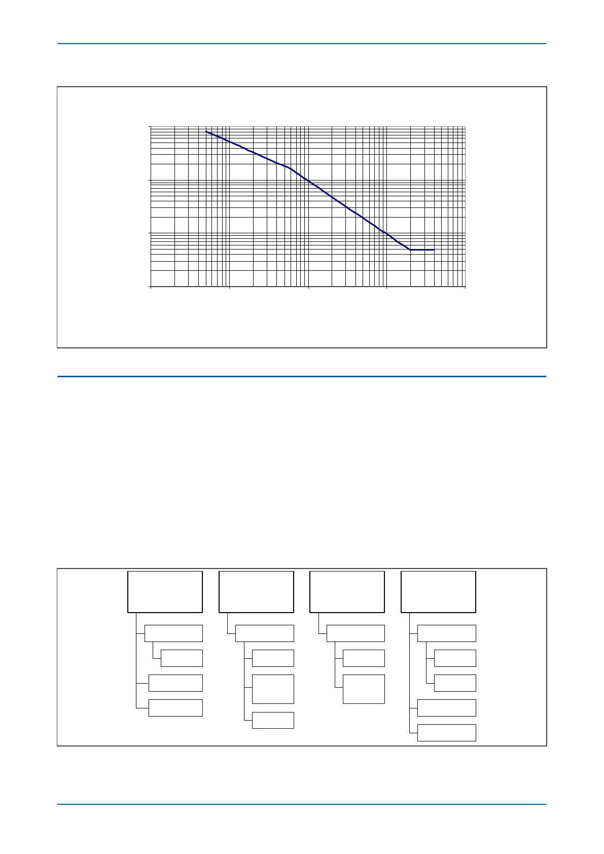
EPATR Curve
1
10
1
00
1000
0.1 1 10 100 1000
Current in Primary A (CT Ratio 100A/1A)
T
i
m
e
i
n
S
e
c
s
V00616
Figure 60: EPATR B characteristic shown for TMS = 1.0
11.5 DIRECTIONAL ELEMENT
Where current may flow in either direction, directional control should be used.
A directional element is av
ailable for all of the SEF overcurrent stages. This is found in the ISEF>(n) Direction cell for
the relevant stage. It can be set to non-directional, directional forward, or directional reverse.
Directionality is achieved by using different techniques depending on the application. With reference to the figure
below, you can see that directional SEF can be used for:
● Solidly earthed systems
● Unearthed systems (insulated systems)
● Compensated systems
● Resistance earthed systems
The following diagram shows which type of directional control can be used for which systems.
Solidly Earthed Systems
Unearthed Systems
(insulated systems)
Compensated Systems
(Petersen coil)
Resistance-Earthed Systems
Directional
Ea
rth Fault
Directional SEF Directional SEF
INsin(j)
c
haracteristic
Wattmetric
V
N
x IN sin (j)
(reactive power)
INcos(j)
c
haracteristic
Wattmetric
V
N
x IN cos (j)
(active power)
Directional SEF Directional SEF
High Impedance Fault
(HI
F)
INcos(j)
c
haracteristic
High Impedance Fault
(HI
F)
Directional
Ea
rth Fault
Core-balanced
CT
Core-balanced
CT
Core-balanced
CT
V00655
Figure 61: Types of directional control
Chapter 6 - Current Protection Functions P14x
132 P14xEd1-TM-EN-1
 Loading...


