The average rate of change of frequency is then measured based on the frequency difference, ∆f over the settable
time period, ∆t
.
The following settings are relevant for Df/Dt protection:
● f+Df/Dt (n) Status: determines whether the stage is for falling or rising frequency conditions
● f+Df/Dt (n) Freq: defines the frequency pickup setting
● f+Df/Dt (n) Dfreq: defines the change in frequency that must be measured in a set time period
● f+Df/Dt (n) Dtime: sets the time period over which the frequency is monitiored
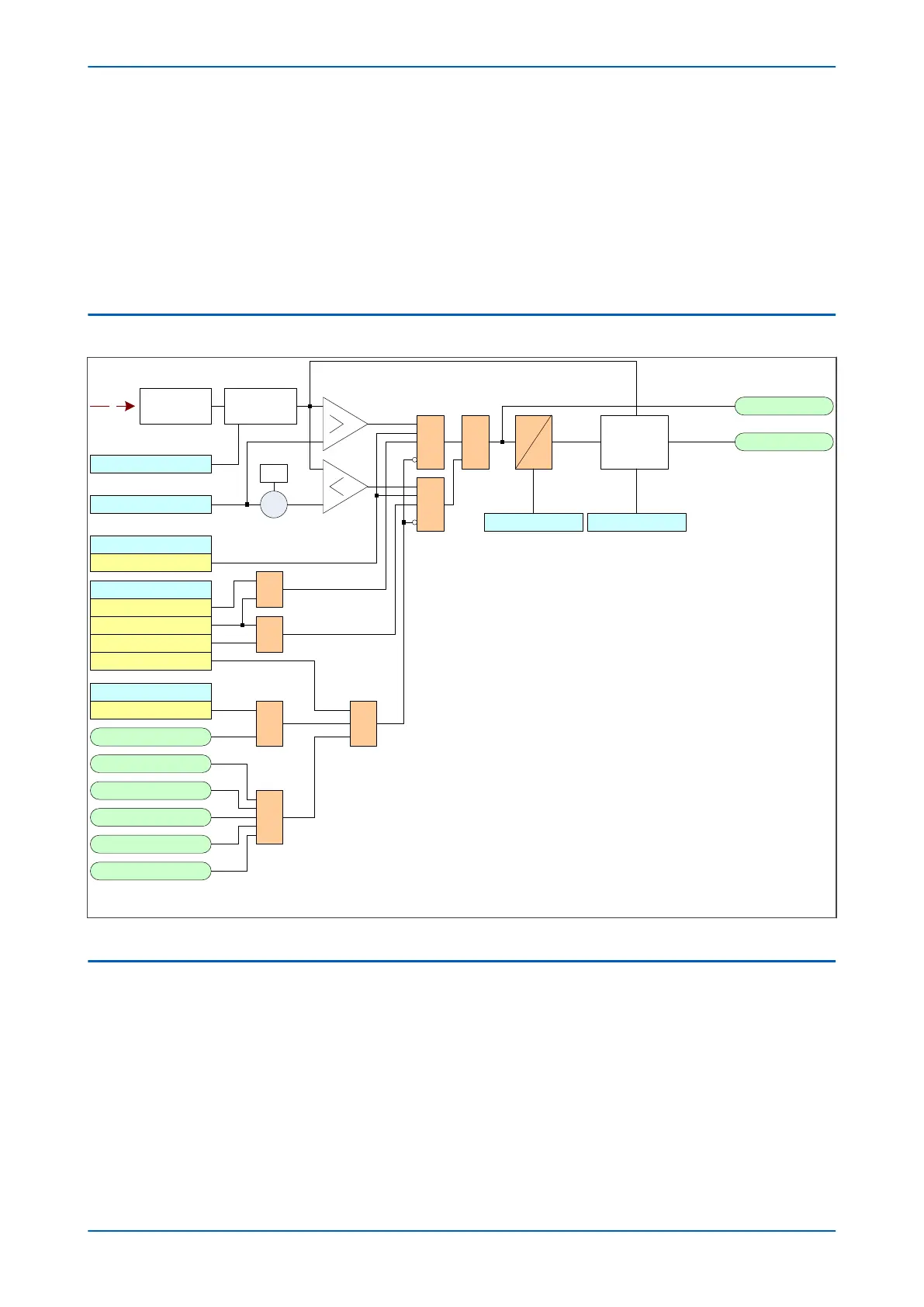
7.2 AVERAGE R.O.C.O.F LOGIC
f+Df/Dt 1 Status
Stg1 df/dt+t Trp
Stage 1
V00859
V
Stg1 df/dt+t Sta
&
Enabled
Adv Freq Inh
Freq Not Found
V<B Status
Enabled
UV Block
1
Frequency
Averaging
f+Df/ Dt 1 freq
X
-1
&
Both
Positive
Negative
Stg1 Block
1
1
1
Freq Avg.Cycles
1
f+Df/Dt 1 Dtime
Frequency
determination
Disabled
Freq High
Freq Low
1
Frequency
comparision
f+Df/Dt 1 Dtime
Note: This diagram does not show all stages . Other stages follow similar principles.
Figure 133: Average rate of change of frequency logic (single stage)
7.3 APPLICATION NOTES
7.3.1 SETTING GUIDELINES
The average rate of change of frequency element can be set to measure the rate of change over a short period as
low as 20
ms (1 cy
cle @ 50 Hz) or a relatively long period up to 2 s (100 cycles @ 50 Hz). With a time setting, Dt,
towards the lower end of this range, the element becomes similar to the frequency supervised rate of change
function, "f+df/dt". With high Dt settings, the element acts as a frequency trend monitor.
Although the element has a wide range of setting possibilities we recommend that the Dt setting is set greater
than 100 ms to ensure the accuracy of the element.
P14x Chapter 11 - Frequency Protection Functions
P14xEd1-TM-EN-1 249
 Loading...


