3 CURRENT TRANSFORMER SUPERVISION
The Current Transformer Supervision function (CTS) is used to detect failure of the AC current inputs to the
protection. This may be caused by internal curr
ent transformer faults, overloading, or faults on the wiring. If there
is a failure of the AC current input, the protection could misinterpret this as a failure of the actual phase currents
on the power system, which could result in maloperation. Also, interruption in the AC current circuits can cause
dangerous CT secondary voltages to be generated.
3.1 CTS IMPLEMENTATION
If the power system currents are healthy, no zero sequence voltage are derived. However, if one or more of the AC
current inputs ar
e missing, a zero sequence current would be derived, even if the actual power system phase
currents are healthy. Standard CTS works by detecting a derived zero sequence current where there is no
corresponding derived zero sequence voltage.
The voltage transformer connection used must be able to refer zero sequence voltages from the primary to the
secondary side. Therefore, this element should only be enabled where the VT is of a five-limb construction, or
comprises three single-phase units with the primary star point earthed.
The CTS function is implemented in the SUPERVISION column of the relevant settings group, under the sub-heading
CT SUPERVISION.
The following settings are relevant for CT Supervision:
● CTS Status: to disable or enable CTS
● CTS VN< Inhibit: inhibits CTS if the zero sequence voltage exceeds this setting
● CTS IN> Set: determines the level of zero sequence current
● CTS Time Delay: determines the operating time delay
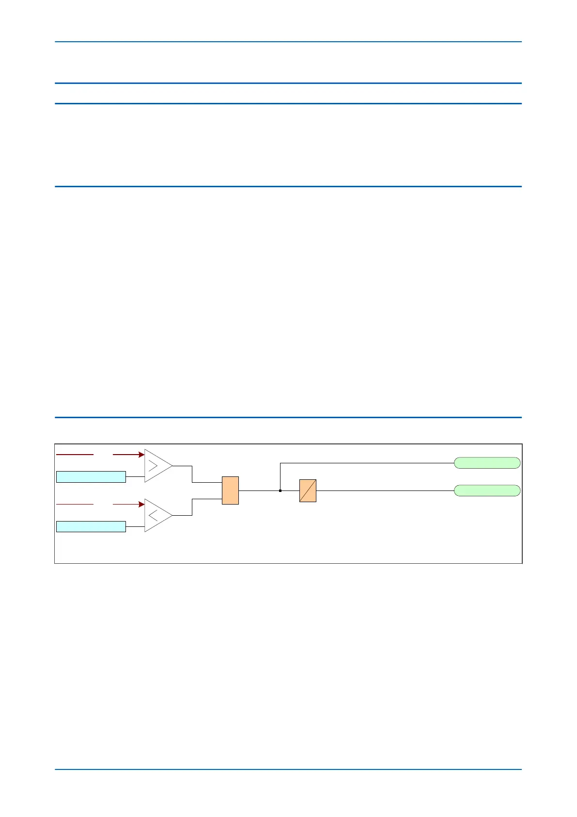
3.2 CTS LOGIC
CTS IN> Set
CTS VN< Inhibit
CTS Block
CT Fail Alarm&
V01203
IN2
VN
Figure 176: CTS logic diagram
If the derived earth fault current (zero sequence current) exceeds the threshold set by CTS IN> Set, a CTS block
DDB signal is produced, provided it is not inhibited. the signal is inhibited if the residual voltage is less than the
threshold set by CTS VN< Inhibit. A CTS alarm is generated after a short time delay defined by the setting CTS
Time Delay.
Chapter 15 - Supervision P14x
348 P14xEd1-TM-EN-1
 Loading...


