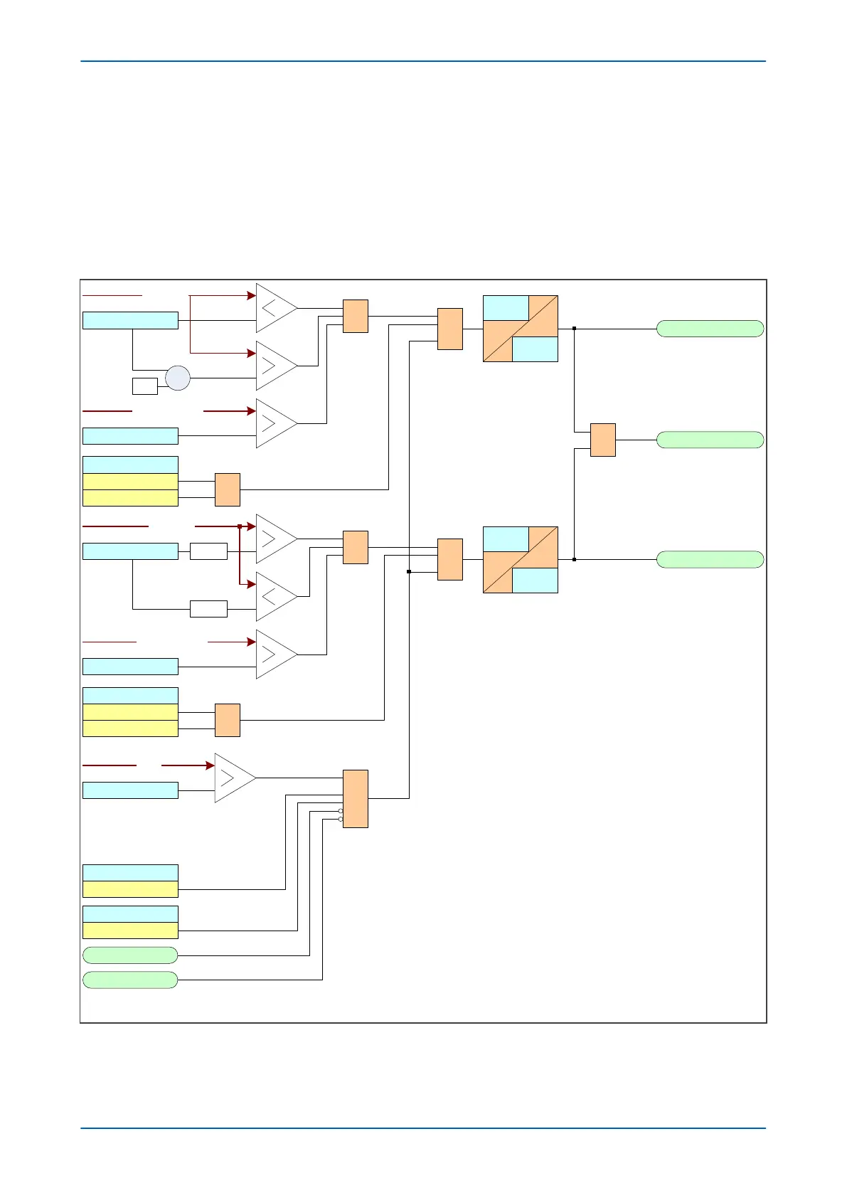
For the forward direction, the positive sequence impedance magnitude is compared with a set value, and the
positive sequence impedance angle is compar
ed with two values, which define the angular range. If the criteria
are satisfied and the Blinder mode is in the direction Forward or Both, the blinder signals Z1 FWD Blinder and Z1
LoadBlinder are produced.
For the reverse direction, the positive sequence impedance magnitude is compared with a set value, and the
positive sequence impedance angle is compared with two values, which define the angular range. If the criteria
are satisfied and the Blinder mode is in the direction Forward or Both, the blinder signals Z1 REV Blinder and Z1
LoadBlinder are produced.
A FWD Blinder
A LoadBlinder
FWD Z Angle
&
FWD Z Impedance
1
V00651
Drop off
Cycles
Pick up
Cycles
-1
X
Blinder Mode
Forward
1
Both
A REV Blinder
REV Z Angle
&
REV Z Impedance
Drop off
Cycles
Pick up
Cycles
+180°
Blinder Mode
Reverse
1
Both
-180°
&
&
Blinder Function
1ph(based on Z )
Blinder Status
Enabled
Blinder V< Block
VTS Slow Block
CTS Block
&
Z Angle
Z1 Magnitude
Z Angle
Z Magnitude
V1
Figure 80: Load Blinder logic phase A
Chapter 6 - Current Protection Functions P14x
154 P14xEd1-TM-EN-1
 Loading...


